


 307 / 1144

Products designed for industrial applications.
General terms and conditions for sale are available on
www.camozzi.com.Series CST-CSV-CSH proximity switches
CATALOGUE
1
/9.05.03
1
>
Release 8.7
MOVEMENT >
MOVEMENT
The Reed version with 3 wires allows the connection of several
sensors in series, as there is no voltage drop between the
supply and the load (see connecting scheme).
The voltage drop is 2,8V for the Reed sensors with 2 wires and
1V for Hall effect sensors with 3 wires.
BN = brown
BU = blue
BK = black
L = load
Connecting schemes in series
The magnetic sensors consist of a reed switch which is
enclosed in a glass bulb containing a rarified gas. The
contacts, which are made of magnetic material (nickel-iron),
are flexible and are coated, at the contact points with a high
quality non-arcing material.
Switching is effected by means of a suitable magnetic field
and actuation is achieved by means of the permanent magnet
inside the piston. The two sensors are of the normally open
type and, therefore, when they are subject to the effect of the
magnetic field, they close the circuit.
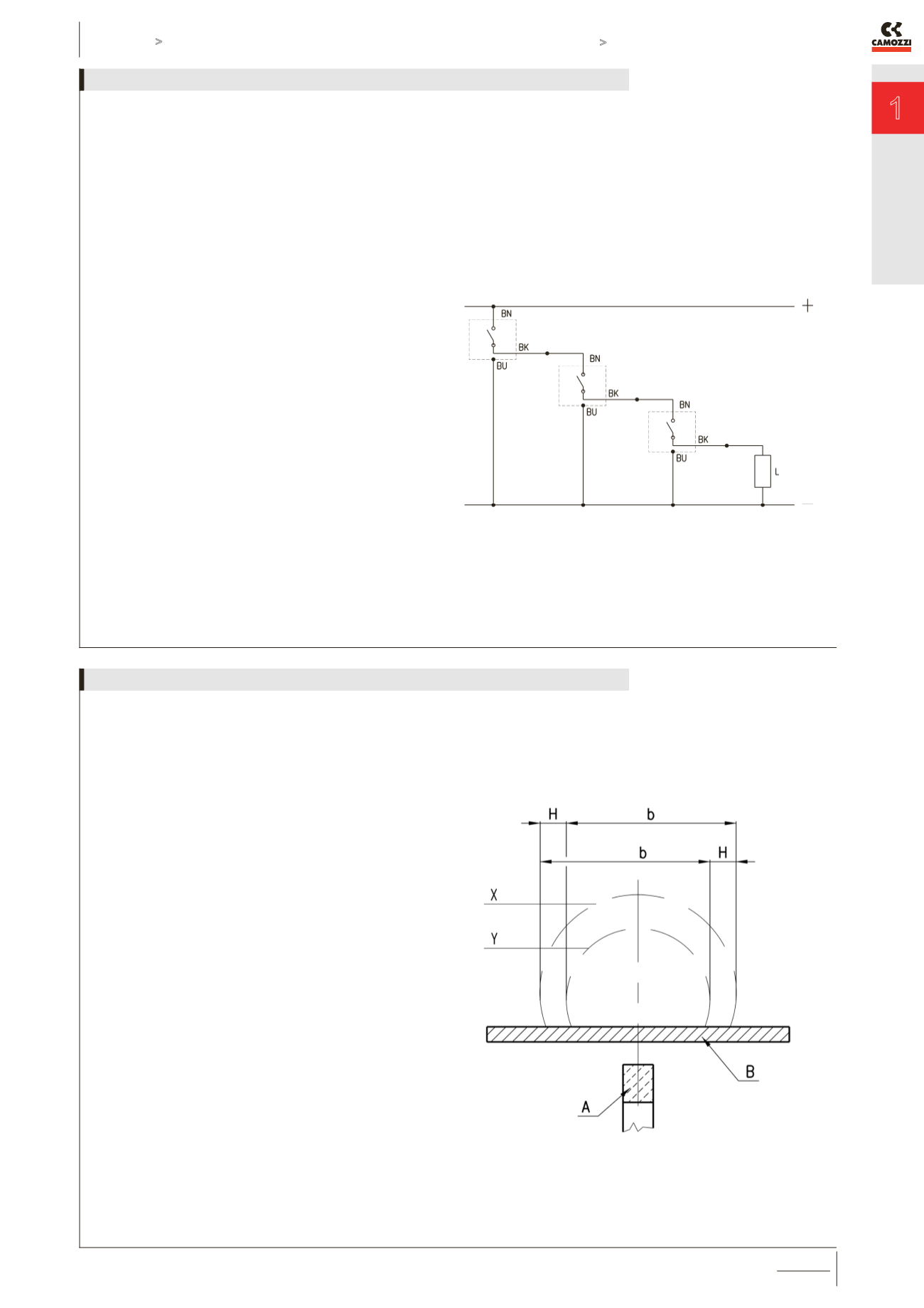
The operating field of the sensors with respect to the magnetic
piston is shown in this picture. The dimension b indicates the
amplitude of the magnetic field or switching field during which
the circuit is closed. The value H represents the operational
hysteresis of the sensor with respect to the form and amplitude
of the magnetic field. The operating field, as a result of
hysteresis, is displaced by the dimension H in the opposite
direction to movement of the piston.
The values b and H are shown in the table and are classified
according to bore.
The maximum speed permitted for each cylinder is a function of
the value b and the response time of the various components
connected after the sensor.
The maximum speed for a cylinder guided by magnetic sensors
is calculated as follows: b / t = Speed
where: b = contact stroke in mm (see table)
t = total reaction time in milli seconds of electric control
components connected after the sensor
Speed = maximum speed in m/second
Useful information for correct use of the magnetic sensors