


 596 / 1144

Products designed for industrial applications.
General terms and conditions for sale are available on
www.camozzi.com.2
Series H valve islands
CONTROL >
CATALOGUE
>
Release 8.7
/3.15.11
2
CONTROL
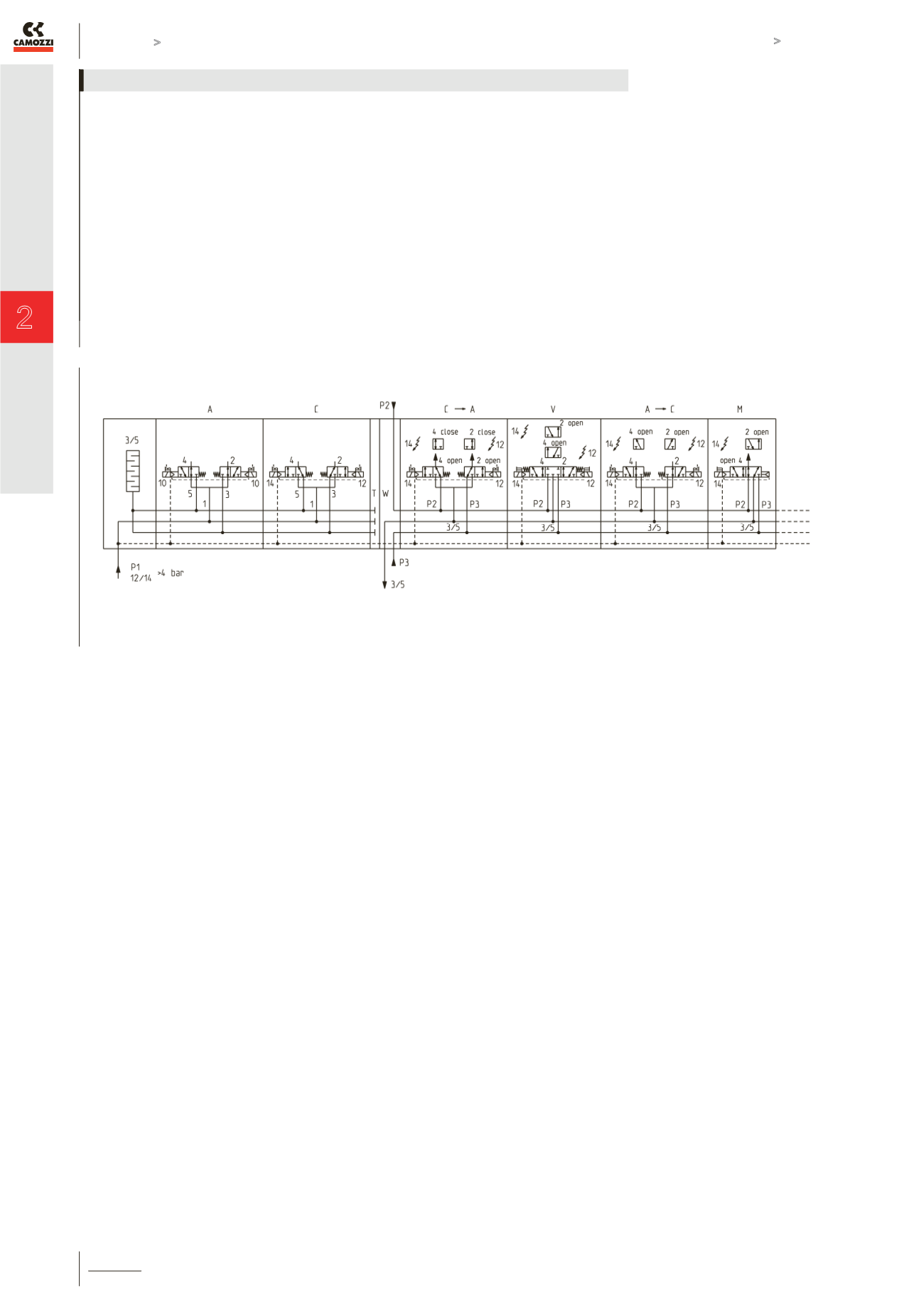
The plate W allows to supply the solenoid valves positioned successively through the exhausts and with different pressures between
them. The air inlets (such as P2 and P3) are in the upper plate whereas the exhaust 3/5 is on the connection 1 on the subbase which
is also used in other configurations.
Solenoid valves supplied from the exhausts work diffently compared with their identification code. Some examples:
solenoid valve mod. C at rest has outlets 2 and 4 active and corresponds to model “A”, in presence of electrical inputs 12 and
14 outlets 2 (P3) and 4 (P2) close respectively; the configuration of solenoid valve mod. V at rest doesn’t change, in presence of
electrical input 12 outlet 4 (P2) is activated, in presence of electrical input 14 outlet 2 (P3) is activated; outlets 2 and 4 are closed in
solenoid valve mod. A at rest which corresponds to model “C”, in presence of electrical inputs 12 and 14 outlets 2 (P3) and 4 (P2)
open respectively; outlet 4 (P2) is active in solenoid valve mod. M at rest, in presence of electrical input 14 the active outlet becomes
outlet 2 (P3).
All the valve functions, both 10.5 and 21 sizes, have this different operation. Solenoid valves with an integrated pressure regulator
can’t be used after an intermediate plate W. This plate requires in the initial part of the valve island a supply pressure of 4 bar at
least. Otherwise, it is necessary to use the version with external servo pilot supply and apply a pressure of at least 4 bar on the
connection 12/14. Before the plate W the insertion of a type T seal is required.
Proper use of valve functions with intermediate plate type W