


 872 / 1144

Products designed for industrial applications.
General terms and conditions for sale are available on
www.camozzi.com.3
Series MC coalescing filters
TREATMENT >
CATALOGUE
>
Release 8.7
/2.10.03
3
TREATMENT
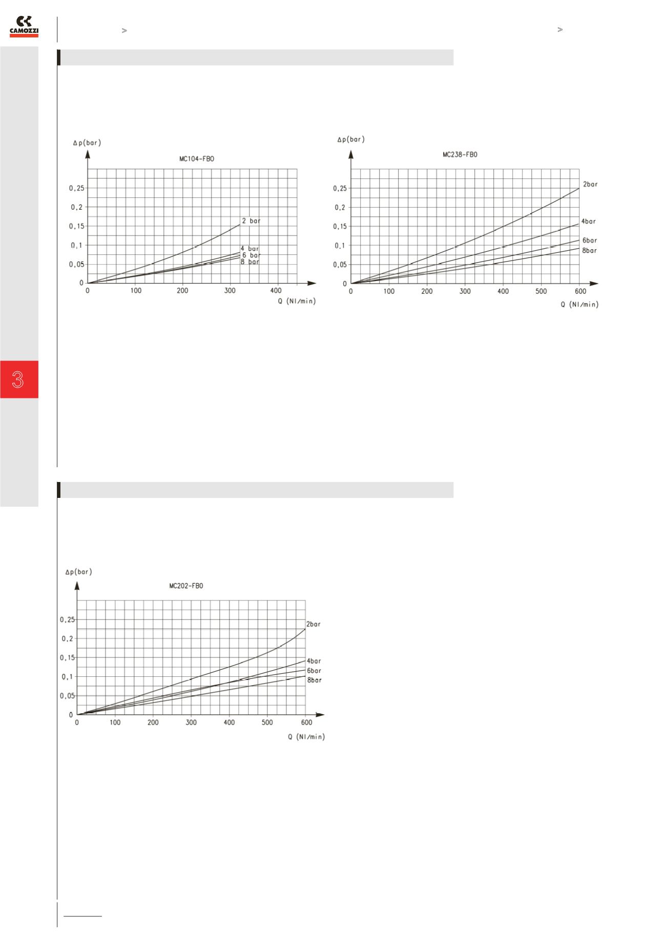
Flow diagram for model: MC104-FB0
ΔP = Pressure drop
Q = Flow
In order to guarantee the indicated performances, the maximum
flow of the filter must be the one indicated in the graph. A higher
flow rate is possible but the same performances are not guaren-
teed.
Flow diagram for model: MC238-FB0
ΔP = Pressure drop
Q = Flow
In order to guarantee the indicated performances, the maximum
flow of the filter must be the one indicated in the graph. A higher
flow rate is possible but the same performances are not guaren-
teed.
FLOW DIAGRAMS
Flow diagram for model: MC202-FB0
ΔP = Pressure drop
Q = Flow
In order to guarantee the indicated performances, the maximum
flow of the filter must be the one indicated in the graph. A higher
flow rate is possible but the same performances are not guaren-
teed.
FLOW DIAGRAMS