


 233 / 1144

Produits pour utilisation industrielle avec air comprimé exclusivement.
Pour tout autre environnement ou fluide, nous consulter.
Conditions générales de vente et de garantie disponibles sur
www.camozzi.com.Vérins rotatifs Série 30
CATALOGUE
1
/6.15.03
1
>
Version 8.7
MOUVEMENT >
MOUVEMENT
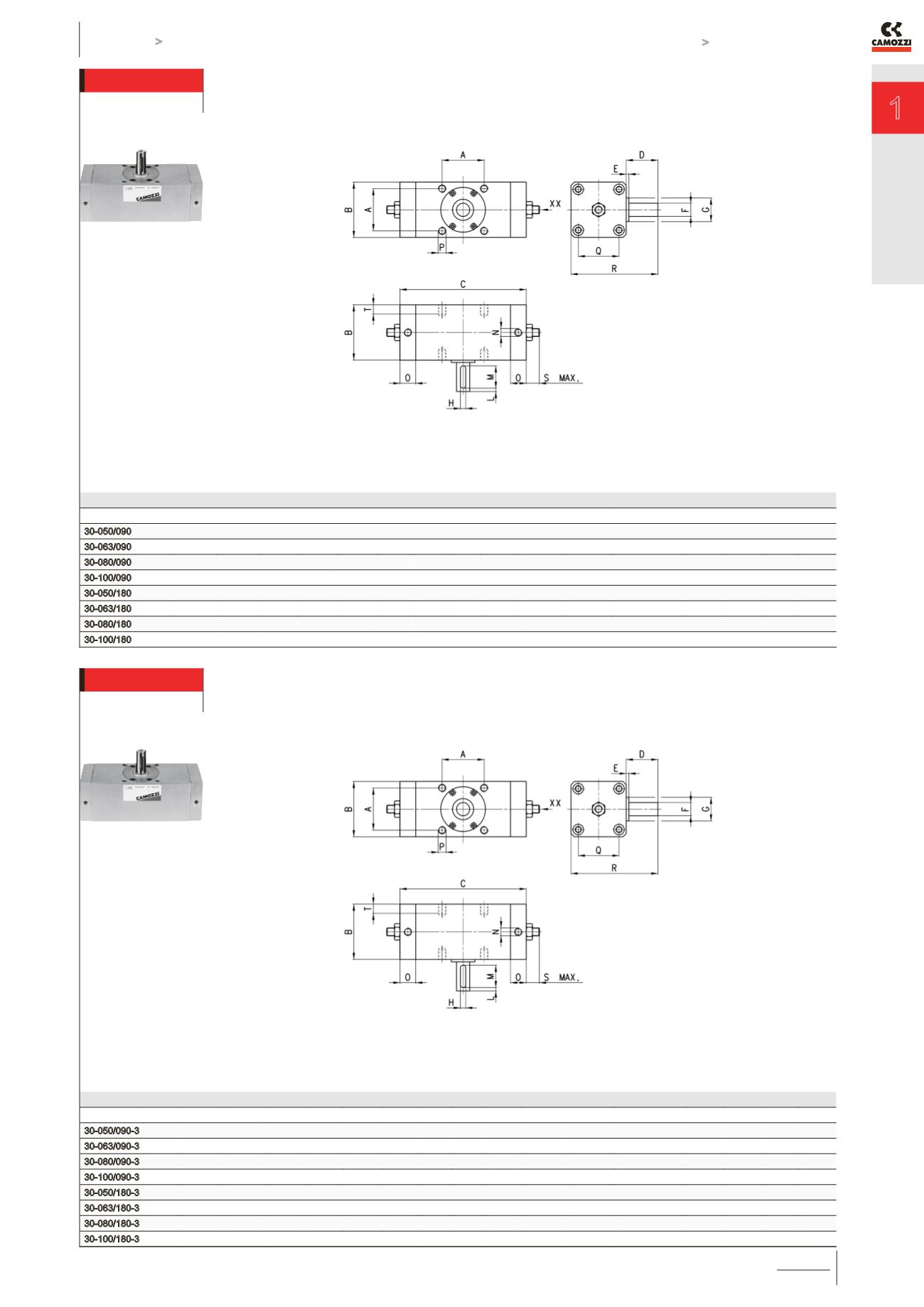
Vérins rotatifs Série 30
DIMENSIONS
Mod.
A
B
C
D E F
h7
G H L
M N
O
P
Q R S T
30-050/090 48
62
162
36
2.5
15
25
5
5
25
G1/8
23
M8 x 1.25
46
98
8
8
30-063/090 60
76
186
41
2.5
17
30
6
5
30
G1/8
24
M10 x 1.5
57
117
8
12
30-080/090 72
92
195
50
3
20
35
6
5
35
G1/4
23,5
M12 x 1.75
70
142
9
13
30-100/090 85
112
247
60
4
25
40
8
5
40
G3/8
26
M12 x 1.75
85
172
9
14
30-050/180 48
62
199
36
2.5
15
25
5
5
25
G1/8
26
M8 x 1.25
46
98
8
8
30-063/180 60
76
237
41
2.5
17
30
6
5
30
G1/8
24
M10 x 1.5
57
117
8
12
30-080/180 72
92
245
50
3
20
35
6
5
35
G1/4
23,5
M12 x 1.75
70
142
9
13
30-100/180 85
112
313
60
4
25
40
8
5
40
G3/8
26
M12 x 1.75
85
172
9
14
XX = Vis de réglage de
l’angle de rotation
* = augmentation de
“C” pour chaque 90° de
rotation.
Vérins rotatifs Série 30
DIMENSIONS
Mod
A
B
C
D E F
h7
G H L
M N
O
P
Q R S T
30-050/090-3 48
62
150
36
2.5
15
25
5
5
25
G1\8
17
M8 x 1.25
46
98
8
8
30-063/090-3 60
76
172
41
2.5
17
32
6
5
30
G1\8
17
M10 x 1.5
57
117
8
12
30-080/090-3 72
92
191
50
3
20
35
6
5
35
G1\4
21,5
M12 x 1.75
70
142
9
13
30-100/090-3 85
112
245
60
4
25
40
8
5
40
G3\8
25
M12 x 1.75
85
172
9
14
30-050/180-3 48
62
187
36
2.5
15
25
5
5
25
G1\8
17
M8 x 1.25
46
98
8
8
30-063/180-3 60
76
233
41
2.5
17
32
6
5
30
G1\8
17
M10 x 1.5
57
117
8
12
30-080/180-3 72
92
241
50
3
20
35
6
5
35
G1\4
21,5
M12 x 1.75
70
142
9
13
30-100/180-3 85
112
311
60
4
25
40
8
5
40
G3\8
25
M12 x 1.75
85
172
9
14
XX = Vis de réglage de
l’angle de rotation
* = augmentation de
“C” pour chaque 90° de
rotation.