


 545 / 1278

Modell- und Maßänderungen vorbehalten.
Unsere AGBs finden Sie auf
www.camozzi.de.
2
Wegeventile Serie 3
ANSTEUERN >
KATALOG
>
Version 8.8
/2.10.02
2
ANSTEUERN
3
SERIE
3
FUNKTION
3 = 3/2 NC
4 = 3/2 NO
5 = 5/2
6 = 5/3 Mitte geschlossen
7 = 5/3 Mitte offen
8 = 5/3 Mitte belüftet
9 = 1x3/2 NC + 1x3/2NO
8
ANSCHLÜSSE
8 = G1/8”
4 = G1/4”
D
AUSFÜHRUNG
= Standard
D = Doppelventil (2x3/2)
L = zur Montage auf Grundplatte (nur für 3/2 G1/8”)
015
BETÄTIGUNG
011 = elektrisch/elektrisch
015 = elektrisch, Federrückstellung
016 = elektrisch/pneumatische Federrückstellung
E11 = 2 Spulen, externe Vorsteuerung
E15 = 1 Spule, externe Vorsteuerung
033 = pneumatisch
035 = pneumatisch/Federrückstellung
02
VORSTEUERVENTIL
02 = Mechanik/Spule 22 x 22 mm
U7
SPULENWERKSTOFF / SPULENABMESSUNGEN
A8 = PPS / 30 x 30 mm
G7 = PA / 22 x 22 mm
G8 = PA / 30 x 30 mm (nur 24 V DC)
G9 = PA / 22 x 58 mm
H8 = PA 6 V0 / 30 x 30 mm
U7 = PET / 22 x 22 mm
7
SPANNUNGEN
siehe Seite 2.2.35.02
AUSFÜHRUNG HANDHILFSBETÄTIGUNG:
= bistabil Standard
IL = bistabil mit Hebel (auf Anfrage)
IM = monostabil (auf Anfrage)
3 3 8 D -
015 -
02 -
U7 7
6512
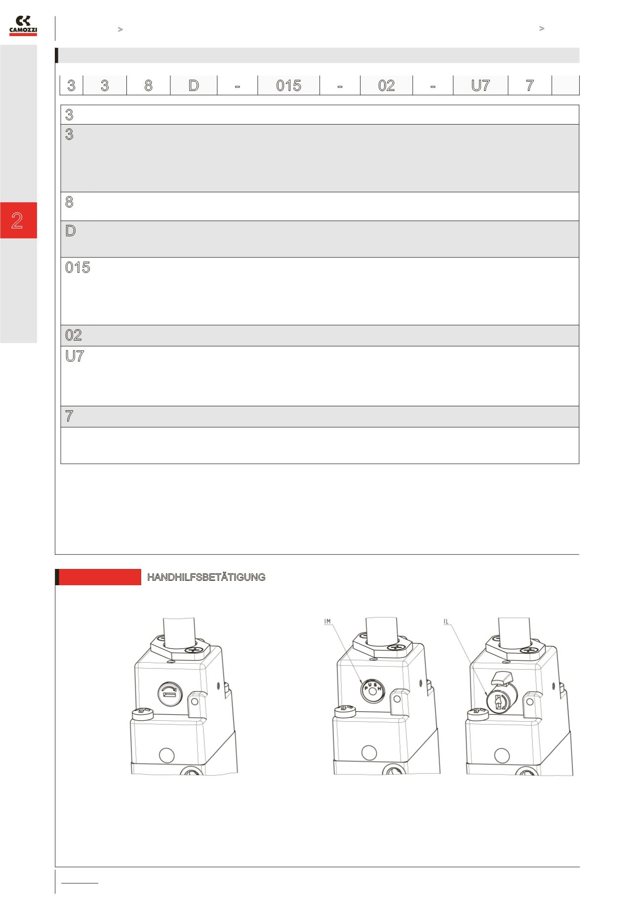
HANDHILFSBETÄTIGUNG
Handhilfsbetätigung Standard
Handhilfsbetätigung monostabil (IM)
Handhilfsbetätigung bistabil (IL)