
Products designed for industrial applications.
General terms and conditions for sale are available on
www.camozzi.com.1
Series 32 cylinders
MOVEMENT >
CATALOGUE
>
Release 8.8
/1.30.02
1
MOVEMENT
STANDARD STROKES FOR CYLINDERS SERIES 32
✖= Non-rotating ●= Double-acting, male/female rod thread;
■= Single-acting, front/rear spring, male/female rod thread.
STANDARD STROKES
Ø
5
10
15
20
25
30
40
50
60
80
20
✖● ■
✖● ■
✖● ■
✖● ■
✖● ■
✖●
✖●
✖●
25
✖● ■
✖● ■
✖● ■
✖● ■
✖● ■
✖●
✖●
✖●
32
✖● ■
✖● ■
✖● ■
✖● ■
✖● ■
✖●
✖●
✖●
✖●
✖●
40
✖● ■
✖● ■
✖● ■
✖● ■
✖● ■
✖●
✖●
✖●
✖●
✖●
50
✖● ■
✖● ■
✖● ■
✖● ■
✖●
✖●
✖●
✖●
✖●
63
✖● ■
✖● ■
✖● ■
✖● ■
✖●
✖●
✖●
✖●
✖●
80
✖● ■
✖● ■
✖● ■
✖● ■
✖●
✖●
✖●
✖●
✖●
100
✖● ■
✖● ■
✖● ■
✖● ■
✖●
✖●
✖●
✖●
✖●
CODING EXAMPLE
32
SERIES
M
VERSION
M = male rod thread, mounted with rod nut Mod. U
F = female rod thread
R = antirotation with flange (not for single-acting version)
2
OPERATION
1 = single-acting, front spring
2 = double-acting
3 = double-acting, through-rod
4 = single-acting, rear spring
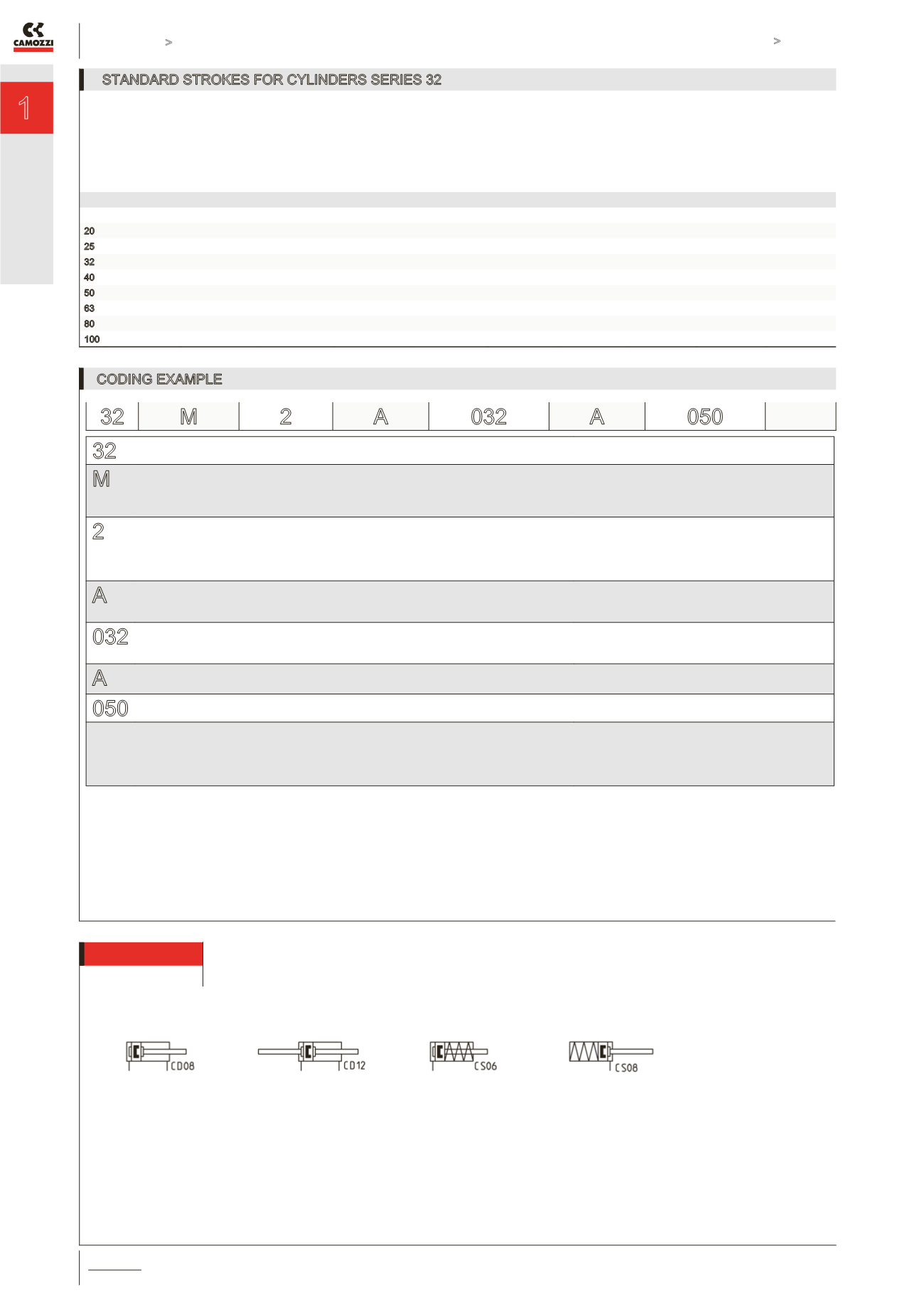
PNEUMATIC SYMBOLS
CS06
CD08
CD12
CS08
A
MATERIALS
A = anodized aluminium body, end blocks and piston,
PU seals (rod, end-blocks OR and piston)
032
BORES
020 = 20 mm - 025 = 25 mm - 032 = 32 mm - 040 = 40 mm
050 = 50 mm - 063 = 63 mm - 080 = 80 mm - 100 = 100 mm
A
CONSTRUCTION
A = standard
050
STROKE (see the table)
= standard
S = special
V = FKM rod seal
W = high temperatures (double-acting, non-magnetic
with FKM seals for high temperatures up to 140°C)
32 M 2
A
032
A
050
PNEUMATIC SYMBOLS
The pneumatic symbols which have been indicated in the CODING EXAMPLE are shown below.


