


 18 / 1278

Products designed for industrial applications.
General terms and conditions for sale are available on
www.camozzi.com.Series 16, 24 and 25 mini-cylinders
CATALOGUE
1
/1.05.02
1
>
Release 8.8
MOVEMENT >
MOVEMENT
STANDARD STROKES FOR MINICYLINDERS SERIES 16 - 24 and 25
■ = Double-acting
✖ = Single-acting
STANDARD STROKES
Series Ø
10
25
40
50
80
100
125
160
200
250
300
320
400
500
16
8
■✖ ■✖ ■✖ ■✖
■
■
■
■
■
16
10
■✖ ■✖ ■✖ ■✖
■
■
■
■
■
16
12
■✖ ■✖ ■✖ ■✖
■
■
■
■
■
■
■
24
16
■✖ ■✖ ■✖ ■✖
■
■
■
■
■
■
■
■
■
■
24
20
■✖ ■✖ ■✖ ■✖
■
■
■
■
■
■
■
■
■
■
24
25
■✖ ■✖ ■✖ ■✖
■
■
■
■
■
■
■
■
■
■
25
16
■
■
■
■
■
■
■
■
■
■
■
■
■
■
25
20
■
■
■
■
■
■
■
■
■
■
■
■
■
■
25
25
■
■
■
■
■
■
■
■
■
■
■
■
■
■
CODING EXAMPLE
24
SERIES
16 = non magnetic
24 = magnetic
25 = magnetic, adjustable cushioning
N
VERSION
N = standard
2
OPERATION
1 = single-acting, front spring, no cushion
2 = double-acting
3 = double-acting, through-rod
7 = single-acting, through-rod
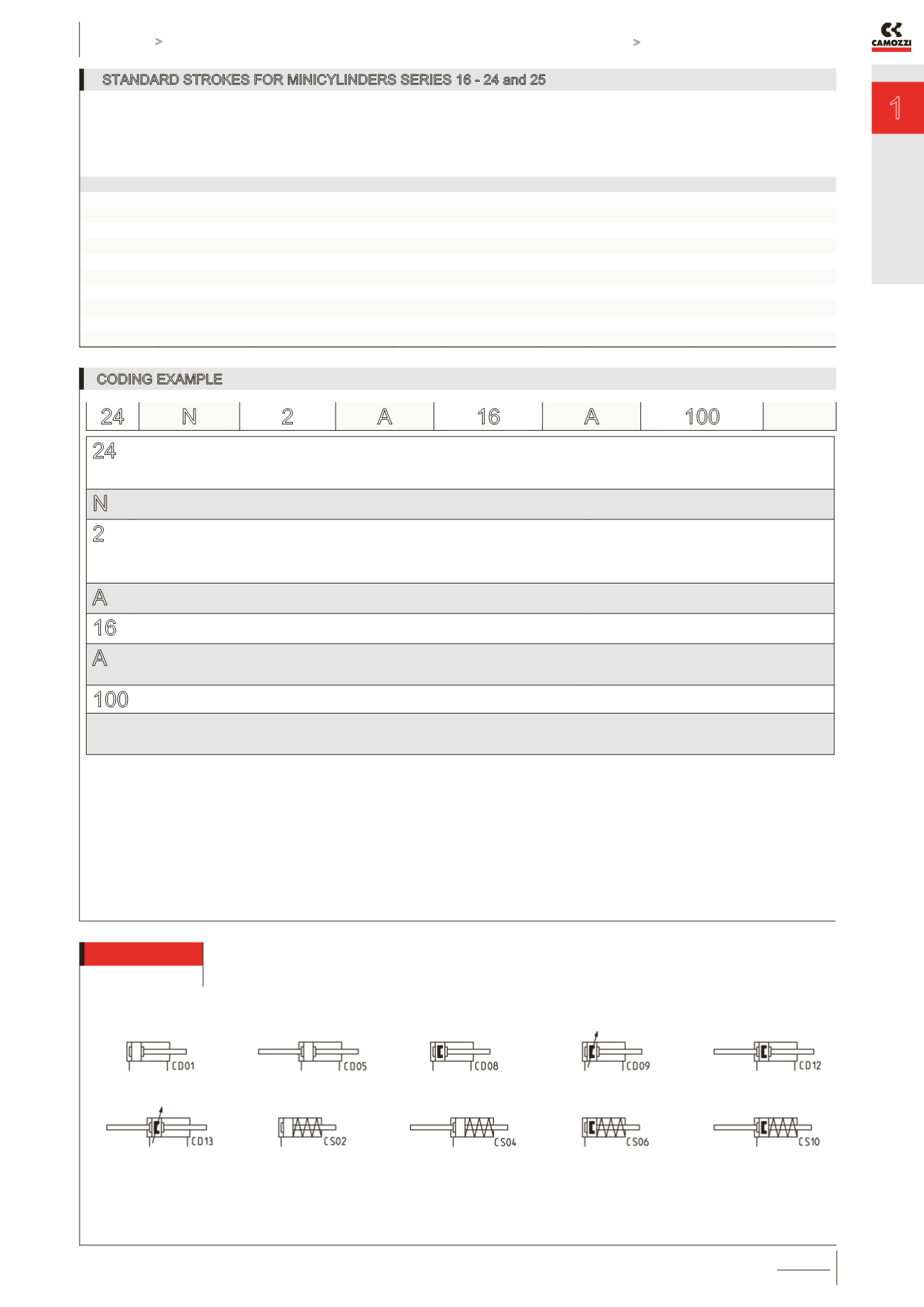
PNEUMATIC SYMBOLS
CS02 (s. 16) - CS06 (s. 24)
CD01 (s. 16) - CD08 (s. 24) - CD09 (s. 25)
CD05 (s. 16) - CD12 (s. 24) - CD13 (s. 25)
CS04 (s. 16) - CS10 (s. 24)
A
MATERIALS
A = rolled stainless steel AISI 303 rod, stainless steel AISI 304 tube, anodized AL end-blocks
16
BORE
08 = 8 mm - 10 = 10 mm - 12 = 12 mm - 16 = 16 mm - 20 = 20 mm - 25 = 25 mm
A
CONSTRUCTION
A = Nose nut Mod. V + Piston rod lock nut Mod. U
RL = cylinder with rod lock ø20 - ø25
100
STROKE (see the table)
= standard
V = rod seal in FKM
W = all seals in FKM, +130°C (for series 25 only)
24 N
2
A
16
A
100
PNEUMATIC SYMBOLS
The pneumatic symbols which have been indicated in the CODING EXAMPLE are shown below.