
Products designed for industrial applications.
General terms and conditions for sale are available on
www.camozzi.com.1
Series QX twin rod cylinders
MOVEMENT >
CATALOGUE
>
Release 8.8
/4.15.04
1
MOVEMENT
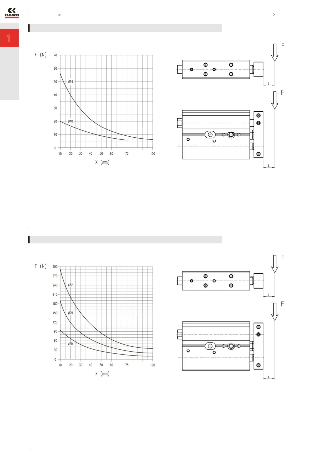
X = cylinder stroke mm.
F = load applied on the flange in N.
Load “ F “ should be considered fixed on the flange of the cylinder
and with a theorical projection of L = 0 mm.
DIAGRAM OF MAX APPLICABLE LOADS DEPENDING ON THE STROKE ( X )
X = cylinder stroke mm.
F = load applied on the flange in N.
Load “ F “ should be considered fixed on the flange of the cylinder
and with a theorical projection of L = 0 mm.
DIAGRAM OF MAX APPLICABLE LOADS DEPENDING ON THE STROKE ( X )


