
Products designed for industrial applications.
General terms and conditions for sale are available on
www.camozzi.com.Series PDV solenoid valves
CATALOGUE
2
/1.19.02
2
>
Release 8.8
CONTROL >
CONTROL
CODING EXAMPLE
PDV
SERIES
C0
BODY DESIGN:
C0 = body with interface for subbase
1
NUMBER OF WAYS - FUNCTIONS:
1 = 2/2-way NC
22
PNEUMATIC CONNECTIONS:
22 = PDV-type interface, 2-way
B7
NOMINAL DIAMETER:
A7 = ø 0.8 mm
B3 = ø 1.2 mm
B7 = ø 1.6 mm
C1 = ø 2.0 mm
3
SEAL MATERIAL:
3 = FKM
4 = EPDM
G
BODY MATERIAL:
G = PEEK
N
MANUAL OVERRIDE:
N = not foreseen
M
FIXING ACCESSORIES:
M = screws for metal
00
OPTIONS:
00 = none
4A
ELECTRICAL CONNECTION:
3A = DIN EN 175 301-803-C (8 mm)
4A = industrial standard (9.4 mm)
7A = cables (L = 300 mm)
3C = DIN EN 175 301-803-C (8 mm) with coil rotated 180°
4C = industrial standard (9.4 mm) with coil rotated 180°
7C = cables (L = 300 mm) with coil rotated 180°
C023
VOLTAGE - POWER CONSUMPTION:
C017 = 6V DC 2W
C020 = 12V DC 2W
C023 = 24V DC 2W
PDV C0 1 22 - B7 3 G N - M 00 4A C023
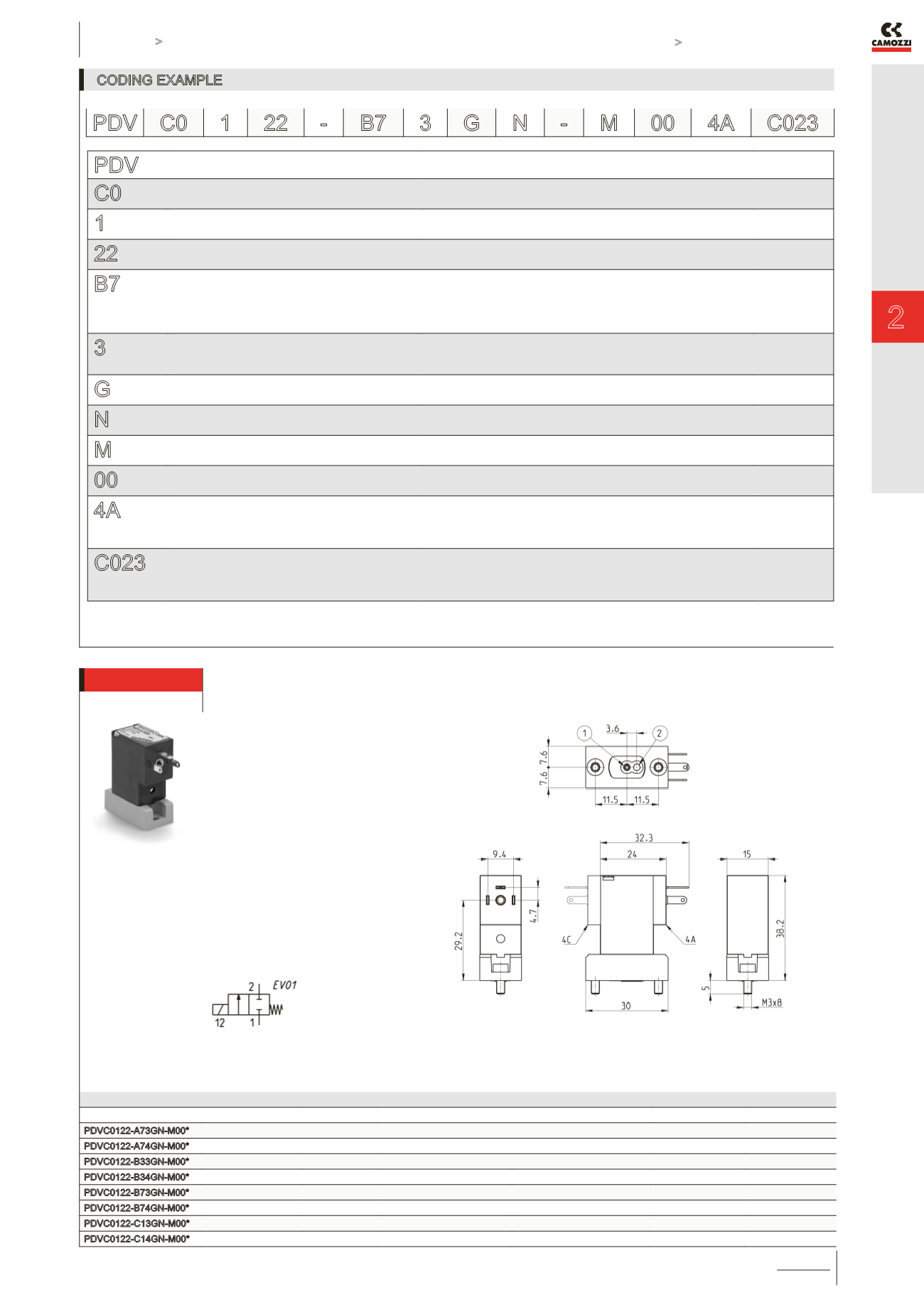
2/2 NC solenoid valve, industrial standard (9.4 mm)
Supplied with:
1x seal
2x M3x8 UNI 5931 screws
NOTE IN THE TABLE BELOW:
* to complete the code, add
ELECTRICAL CONNECTION
(4A or 4C options)
and VOLTAGE
(see CODING EXAMPLE)
Mod.
Orifice Ø (mm)
kv (l/min)
Min/max pressure (bar)
Max back pressure (bar)
Body material
Seal material
PDVC0122-A73GN-M00*
0.8
0.25
0 ÷ 7.0
1.2
PEEK
FKM
PDVC0122-A74GN-M00*
0.8
0.25
0 ÷ 7.0
1.2
PEEK
EPDM
PDVC0122-B33GN-M00*
1.2
0.55
0 ÷ 4.5
1.2
PEEK
FKM
PDVC0122-B34GN-M00*
1.2
0.55
0 ÷ 4.5
1.2
PEEK
EPDM
PDVC0122-B73GN-M00*
1.6
0.65
0 ÷ 4.0
1.2
PEEK
FKM
PDVC0122-B74GN-M00*
1.6
0.65
0 ÷ 4.0
1.2
PEEK
EPDM
PDVC0122-C13GN-M00*
2.0
0.80
0 ÷ 3.0
1.2
PEEK
FKM
PDVC0122-C14GN-M00*
2.0
0.80
0 ÷ 3.0
1.2
PEEK
EPDM
NOTE IN THE DRAWING:
1 = INLET PORT
2 = OUTLET PORT


