
Products designed for industrial applications.
General terms and conditions for sale are available on
www.camozzi.com.Adjustable valve Mod. VMR 1/8-B10
CATALOGUE
2
/6.04.02
2
>
Release 8.8
CONTROL >
CONTROL
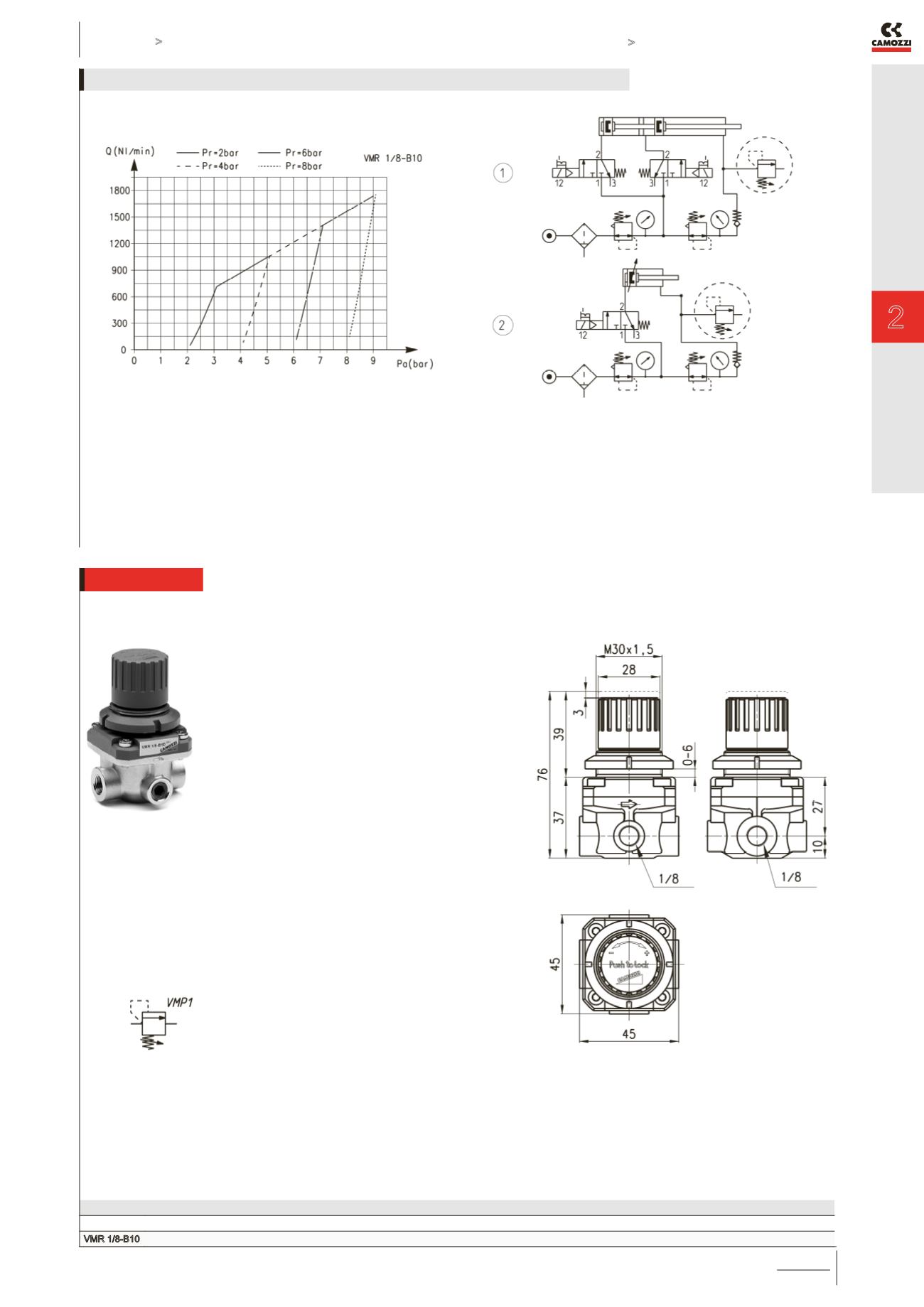
FLOW DIAGRAM
Pa = Inlet pressure
Pr = Regulated pressure
Q = Flow
FUNCTIONING SCHEME 1: overpressure exhaust in a cylinder
chamber or in a tank when the set value has been exceeded.
FUNCTIONING SCHEME 2: VMR valve with maximum
adjustable pressure allows pressure in a cylinder chamber or in
tank to exhaust in the atmosphere every time the set regulation
value is exceeded.
FLOW DIAGRAM and FUNCTIONING SCHEMES
Valve with maximum adjustable pressure Mod. VMR 1/8-B10
Mod.
Working pressure (bar)
VMR 1/8-B10
1 ÷ 8


