


 17 / 84

Products designed for industrial applications.
General terms and conditions for sale are available on
www.camozzi.com.Series 6E electromechanical cylinders
C_Electrics
1
15
>
2017
MOVEMENT >
MOVEMENT
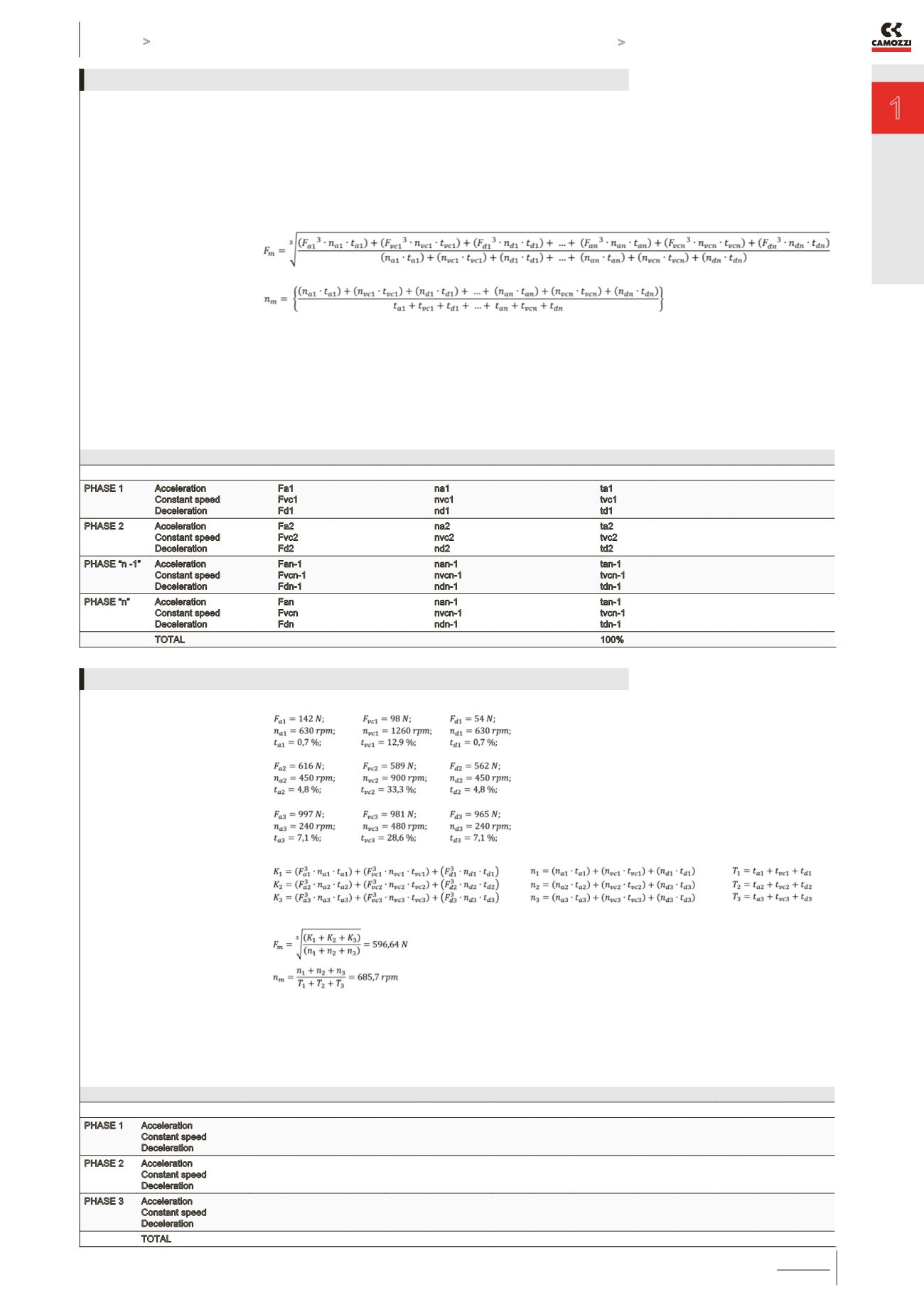
The analysis of the duty cycle and
of the pauses of the system is
essential to calculate the average
Fm axial loads and the number of
average revolutions nm that act on
the cylinder.
Normally, the duty cycle is composed
by phases and for each single
phase, we can have an acceleration,
constant speed or deceleration.
CALCULATION OF THE
AVERAGE AXIAL FORCE
CALCULATION OF THE AVERAGE
NUMBER OF REVOLUTIONS
The table shown below reports the
values of acceleration, speed and
deceleration for each phase.
F [N]
n [rpm]
time %
PHASE 1
Acceleration
Constant speed
Deceleration
Fa1
Fvc1
Fd1
na1
nvc1
nd1
ta1
tvc1
td1
PHASE 2
Acceleration
Constant speed
Deceleration
Fa2
Fvc2
Fd2
na2
nvc2
nd2
ta2
tvc2
td2
PHASE “n -1” Acceleration
Constant speed
Deceleration
Fan-1
Fvcn-1
Fdn-1
nan-1
nvcn-1
ndn-1
tan-1
tvcn-1
tdn-1
PHASE “n”
Acceleration
Constant speed
Deceleration
Fan
Fvcn
Fdn
nan-1
nvcn-1
ndn-1
tan-1
tvcn-1
tdn-1
TOTAL
100%
ANALYSIS OF THE DUTY CYCLE AND OF SYSTEM PAUSES
Phase 1
Phase 2
Phase 3
in this way it is possible to determine:
Concluding, we know that:
F [N]
n [rpm]
time %
PHASE 1 Acceleration
Constant speed
Deceleration
142
98
54
630
1260
630
0.7
12.9
0.7
PHASE 2 Acceleration
Constant speed
Deceleration
616
589
562
450
900
450
4.8
33.3
4.8
PHASE 3 Acceleration
Constant speed
Deceleration
997
981
965
240
480
240
7.1
28.6
7.1
TOTAL
100.0
APPLICATION EXAMPLE