


 33 / 210

28
1
PRODUKTÜBERSICHT
>
Version 8.8
1
ANTREIBEN
Modell- und Maßänderungen vorbehalten.
Unsere AGBs finden Sie auf
www.camozzi.de.
ANTREIBEN >
Serie 69 - Serie 30
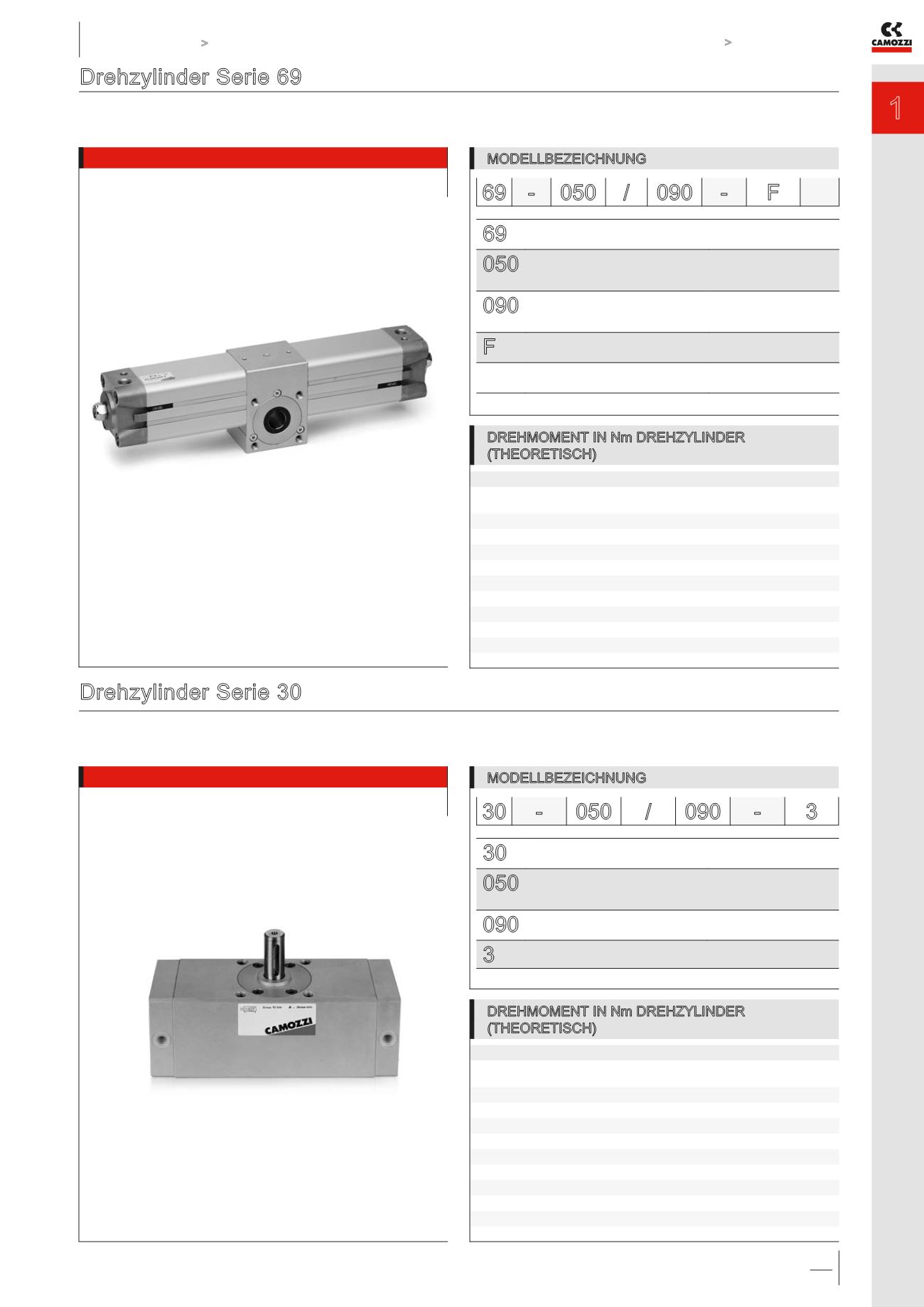
Drehzylinder Serie 69
Magnetversion zur berührungslosen Abtastung mit Endlagendämpfung und Winkelbegrenzung
ø 32, 40, 50, 63, 80, 100, 125 mm
Drehwinkel: 90°, 180°, 270° und 360°
Drehzylinder Serie 30
Mit und ohne Endlagendämpfung
ø 50, 63, 80, 100 mm
Drehwinkel 90° und 180°
MODELLBEZEICHNUNG
69
SERIE
PNEUMATIKSYMBOL *
CD18
050
KOLBENDURCHMESSER:
032 = 32 mm - 040 = 40 mm - 050 = 50 mm - 063 = 63 mm
080 = 80 mm - 100 = 100 mm - 125 = 125 mm
090
DREHWINKEL:
090 = 90° 180 = 180°
270 = 270° 360 = 360°
F
WELLENAUSFÜHRUNG:
F = Hohlwelle - M = Zapfenwelle
WERKSTOFFE DICHTUNGEN:
= NBR - W = FKM +130°C
69 - 050 / 090 -
F
* = Die Übersicht der Pneumatiksymbole finden Sie am Ende dieses Kapitels.
MODELLBEZEICHNUNG
30
SERIE
PNEUMATIKSYMBOL*
CD17
050
DURCHMESSER:
050 = 50 mm - 063 = 63 mm
080 = 80 mm - 100 = 100 mm
090
DREHWINKEL:
090 = 90° - 180 = 180°
3
Nicht gedämpft
30 - 050 /
090 -
3
* = Die Übersicht der Pneumatiksymbole finden Sie am Ende dieses Kapitels.
ø
50
63
80
100
Drehmoment
Nm
1 bar
2,08
4,40
7,10
16,63
2 bar
4,16
8,80
14,19
33,27
3 bar
6,24
13,20
21,29
49,90
4 bar
8,32
17,61
28,39
66,54
5 bar
10,40
22,01
35,49
83,17
6 bar
12,48
26,41
42,58
99,80
7 bar
14,55
30,81
49,68
116,44
8 bar
16,63
35,21
56,78
133,07
9 bar
18,71
39,61
63,87
149,07
10 bar
20,79
44,01
70,97
166,34
ø Zyl.
32
40
50
63
80
100
125
Drehmoment
Nm
1 bar
1,2
2,25
3,9
7,3
15,7 26,35
51
2 bar
2,4
4,5
7,8
14,6
31,4
52,7
102
3 bar
3,6
6,75
11,7
21,9
47,1 79,05 153
4 bar
4,8
9
15,6
29,2
62,8 105,4 204
5 bar
6
11,25 19,5
36,5
78,5 131,75 255
6 bar
7,2
13,5
23,4
43,8
94,2 158,1 306
7 bar
8,4
15,75 27,3
51,1 109,9 184,45 357
8 bar
9,6
18
31,2
58,4 125,6 210,8 408
9 bar
10,8 20,25 35,1
65,7 141,3 237,15 459
10 bar
12
22,5
39
73
157 263,5 510
DREHMOMENT IN Nm DREHZYLINDER
(THEORETISCH)
DREHMOMENT IN Nm DREHZYLINDER
(THEORETISCH)