


 13 / 210

8
1
SHORT FORM CATALOGUE
>
Release 8.8
1
MOVEMENT
Products designed for industrial applications.
General terms and conditions for sale are available on
www.camozzi.com.Mod. B
Mod. S
Mod. GY
Mod. GK
Mod. C and C-H
Mod. H and C-H
Mod. L
Mod. G
Mod. D-E
Mod. ZC
Mod. R Mod. GKF
Mod. 80-62/8C
Mod. C+L+S
Mod. U
Mod. GA
MOVEMENT >
Series 62
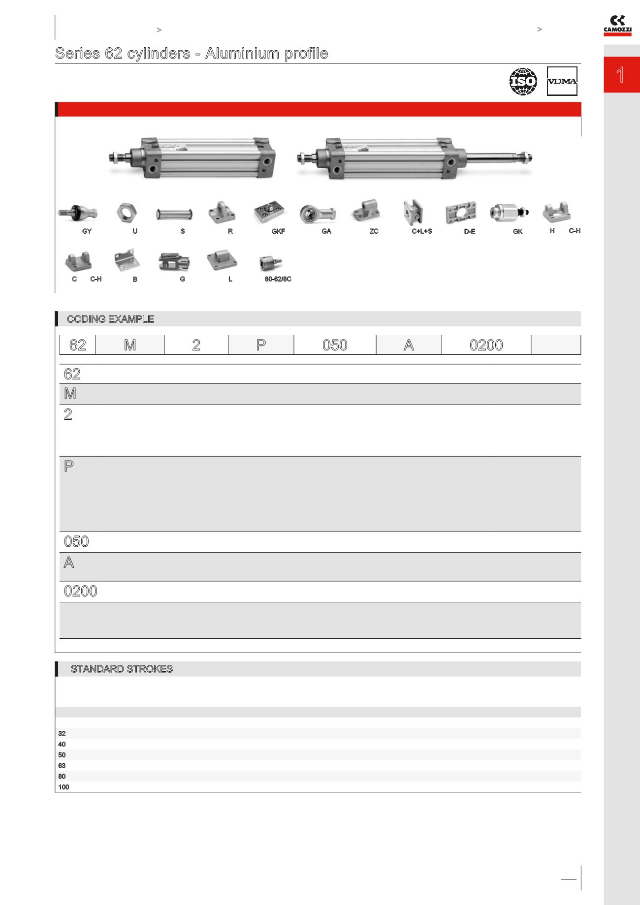
Series 62 cylinders - Aluminium profile
Double-acting, magnetic, cushioned. ISO 15552 - DIN/ISO 6431 / VDMA 24562
ø 32, 40, 50, 63, 80, 100 mm
Example of assembly with a valve on page 11
CODING EXAMPLE
62
SERIES
M
VERSION:
M = standard, magnetic
2
OPERATION:
2 = double-acting, front + rear cushion
3 = double-acting, no cushion
4 = double-acting, rear cushion
5 = double-acting, front cushion
6 = double-acting, through-rod, front + rear cushion
PNEUMATIC SYMBOLS *
CD09
CD08
CD10
CD11
CD13
P
MATERIALS:
P = AL end-blocks, technopolymer piston, rolled stainless steel AISI 420B piston rod, zinc-plated steel piston rod nut, anodized
AL-profile tube, zinc-plated steel tie-rods and nuts, NBR piston rod and piston seals, PU cushion seals (ø 80-100: PU piston seal)
R = stainless steel AISI 420B tie-rods, stainless steel AISI 303 tie-rod nuts
C = rolled stainless steel AISI 303 piston rod , stainless steel AISI 304 piston rod nut
U = rolled stainless steel AISI 303 piston rod, stainless steel AISI 304 piston rod nut,
stainless steel AISI 420B tie-rod, stainless steel AISI 303 tie-rod nuts
W = rolled stainless steel AISI 304 piston rod, stainless steel AISI304 piston rod nut,
stainless steel AISI 420B tie-rods, stainless steel AISI 303 tie-rod nuts
050
BORE:
032 = 32 mm - 040 = 40 mm - 050 = 50 mm - 063 = 63 mm - 080 = 80 mm - 100 = 100 mm
A
CONSTRUCTION:
A = standard lock nut for rod
RL = cylinder with rod lock
0200
STROKE:
10 ÷ 2500 mm
= standard
V = FKM piston rod seal
P = PU piston rod seal
( _ _ _ ) = extended piston rod _ _ _ mm
62 M 2
P
050
A
0200
STANDARD STROKES
✖ = Double-acting
Special strokes until 2500 mm available on request
Ø 25
50
75
80
100
125
150
160
200
250
300
320
400
500
32
✖
✖
✖
✖
✖
✖
✖
✖
✖
✖
✖
✖
✖
✖
40
✖
✖
✖
✖
✖
✖
✖
✖
✖
✖
✖
✖
✖
✖
50
✖
✖
✖
✖
✖
✖
✖
✖
✖
✖
✖
✖
✖
✖
63
✖
✖
✖
✖
✖
✖
✖
✖
✖
✖
✖
✖
✖
✖
80
✖
✖
✖
✖
✖
✖
✖
✖
✖
✖
✖
✖
✖
✖
100
✖
✖
✖
✖
✖
✖
✖
✖
✖
✖
✖
✖
✖
* = The complete list of cylinders pneumatic symbols is available at the end of this chapter