


 187 / 226

f l ow con t ro l v a l v e s & a c c e s sor i e s
4
b s p/me t r i c
The company reserves the right to vary models and dimensions without notice.
These products are designed for industrial applications and are not suitable for sale to the general public.
177
B S P / M E T R I C
Dimensions in millimeters (mm)
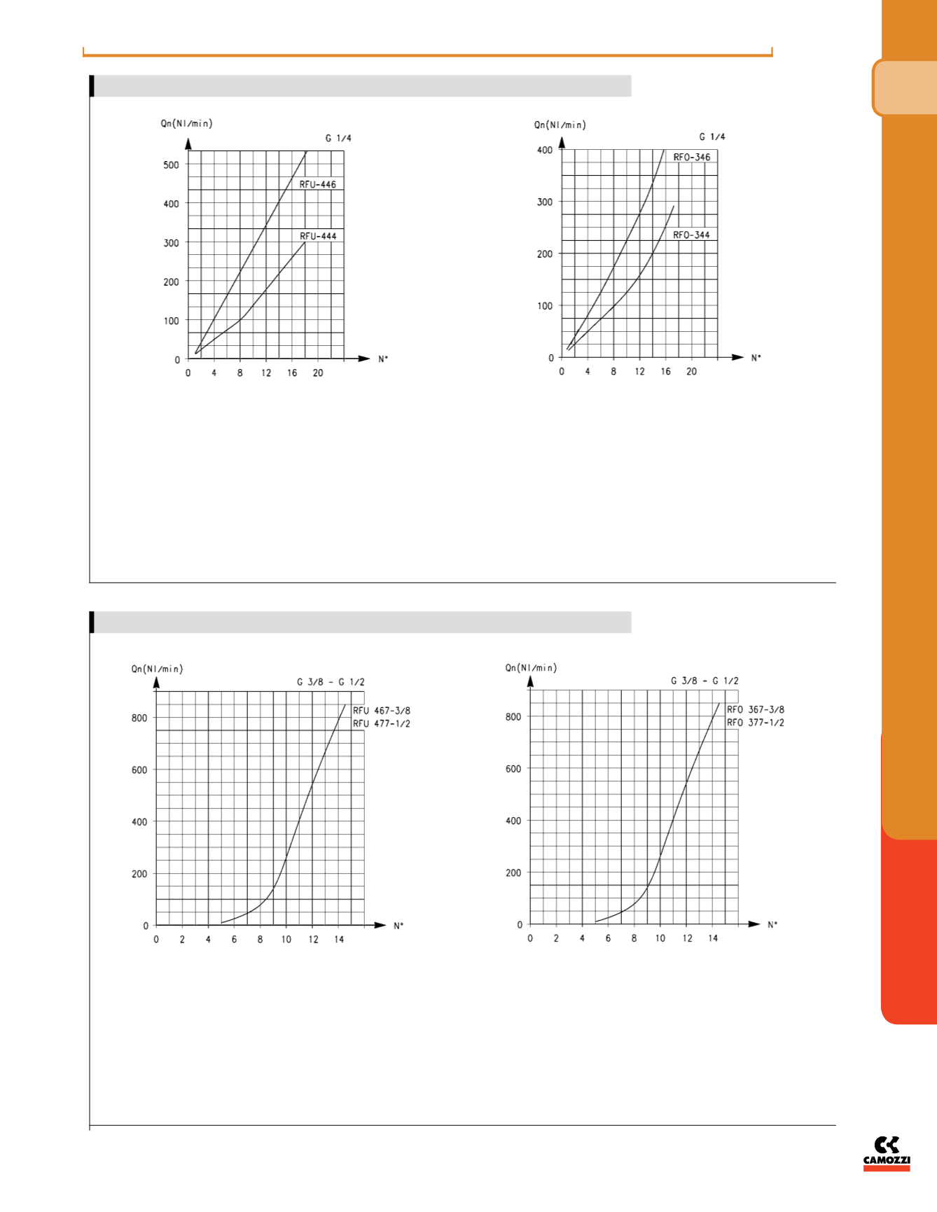
RFU 444-1/4: flow from 2 → 1 needle type OPEN = 680 Nl/min
CLOSED = 534 Nl/min
RFU 446-1/4: flow from 2 → 1 needle type OPEN = 680 Nl/min
CLOSED = 534 Nl/min
N° = number of screw turns
Note: the flow (Qn) is determined with a pressure of 6 bar at the
inlet and ΔP = 1 bar at the outlet.
RFO 344-1/4 - RFO 346-1/4
N° = number of screw turns.
Note: the flow (Qn) is determined with a pressure of 6 bar at the
inlet and ΔP = 1 bar at the outlet.
RFU 467-3/8: flow from 2 → 1 needle type OPEN = 1700 Nl/min
CLOSED = 1700 Nl/min
RFU 477-1/2: flow from 2 → 1 needle type OPEN = 1700 Nl/min
CLOSED = 1700 Nl/min
N° = number of screw turns
Note: the flow (Qn) is determined with a pressure of 6 bar at the
inlet and ΔP = 1 bar at the outlet.
RFO 367-3/8 - RFO 377-1/2
N° = number of screw turns
Note: the flow (Qn) is determined with a pressure of 6 bar at the
inlet and ΔP = 1 bar at the outlet.
FLOW DIAGRAMS (1 → 2) - VALVES SERIES RFU / RFO - G1/4 PORTS
FLOW DIAGRAMS (1 → 2) - VALVES SERIES RFU / RFO - G3/8, G1/2 PORTS