


 779 / 1144

Products designed for industrial applications.
General terms and conditions for sale are available on
www.camozzi.com.Series LR*D2 digital proportional servo valves
CATALOGUE
2
/15.32.05
2
>
Release 8.7
CONTROL >
CONTROL
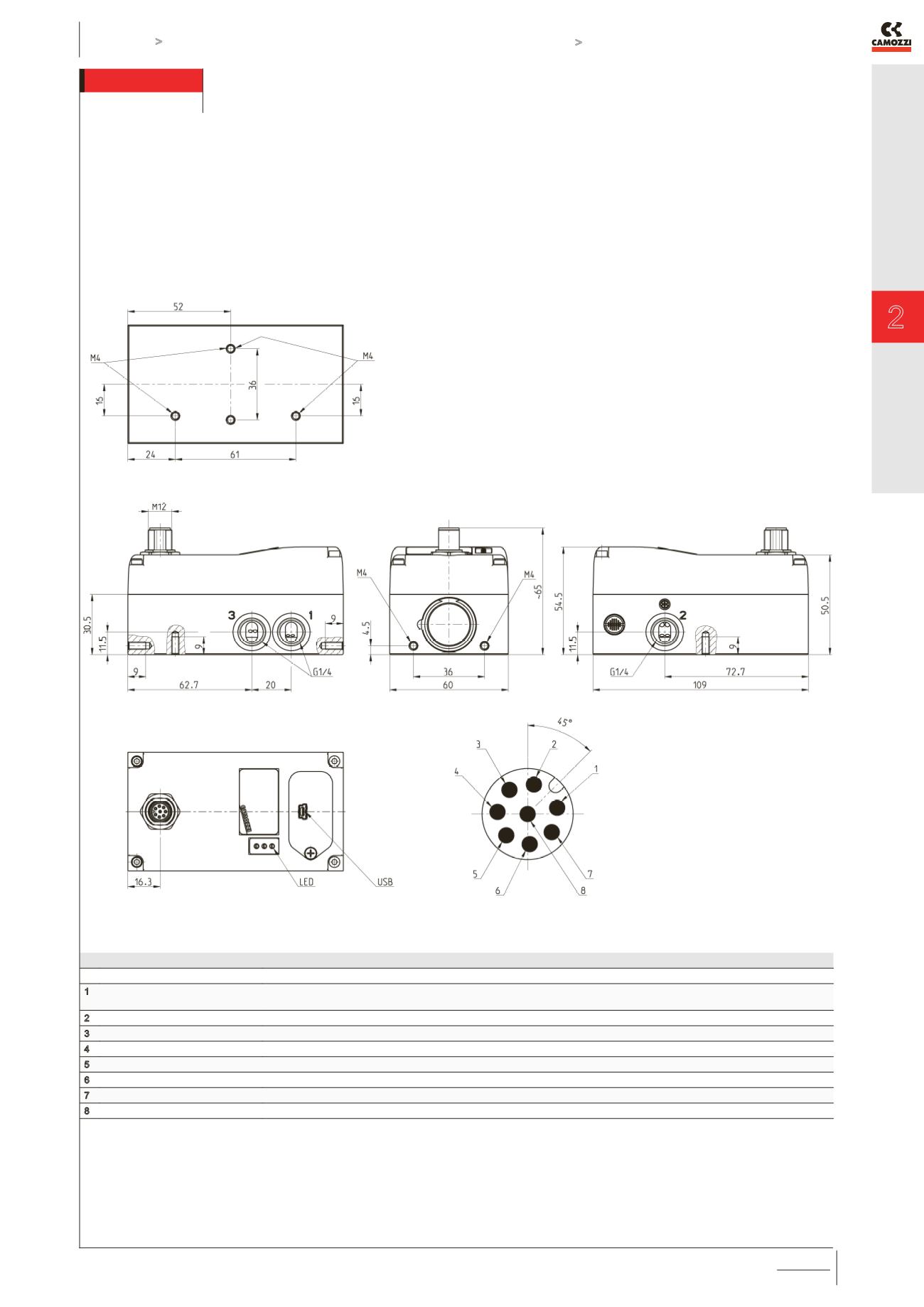
SERIES LRWD2 and LRPD2 - PNEUMATIC INSTALLATION
The servo valve works as follows: if the command
signal or setpoint is lower than 50%, the valve
establishes a link between connection 1 and
connection 2; then the air passes between the inlet
and the outlet. If the setpoint value is higher than
50%, the port 2 is connected with the exhaust 3. For
a better understanding, please see the flow diagram
on the previous page.
PIN
SIGNAL
DESCRIPTION
1
+5V
+5V power supply for external potentiometer transducer (ref. GND).
If used, is necessary to connect RIF- with GND.
2
24 V DC
24V DC power supply (logic and motor): connect to the positive pole of the 24V DC power supply (ref. GND)
3
RIF-
GND reference or NEGATIVE pole of the command signal (0-10V / 4-20mA / ±10V)
4
RIF+
POSITIVE reference of the command signal (0-10V / 4-20mA / ±10V)
5
EXT
Not used
6
FBK
Feedback signal 0-10V / 4-20mA (ref. GND)
7
GND
Common (reference pin 1 and 2): connect to the negative pole of the 24V DC power supply (compulsory)
8
ERR
Error signal (output) 0-24V (ref. GND)
THE LENGTH OF THE LEADS SHOULD BE AS SHORT AS
POSSIBLE, BETWEEN VALVE-OUTLET AND LOAD NORMALLY
NOT MORE THAN 2 mts.