


 774 / 1144

Products designed for industrial applications.
General terms and conditions for sale are available on
www.camozzi.com.2
Series LRXA4 servo valves - Positioning control
CONTROL >
CATALOGUE
>
Release 8.7
/15.30.03
2
CONTROL
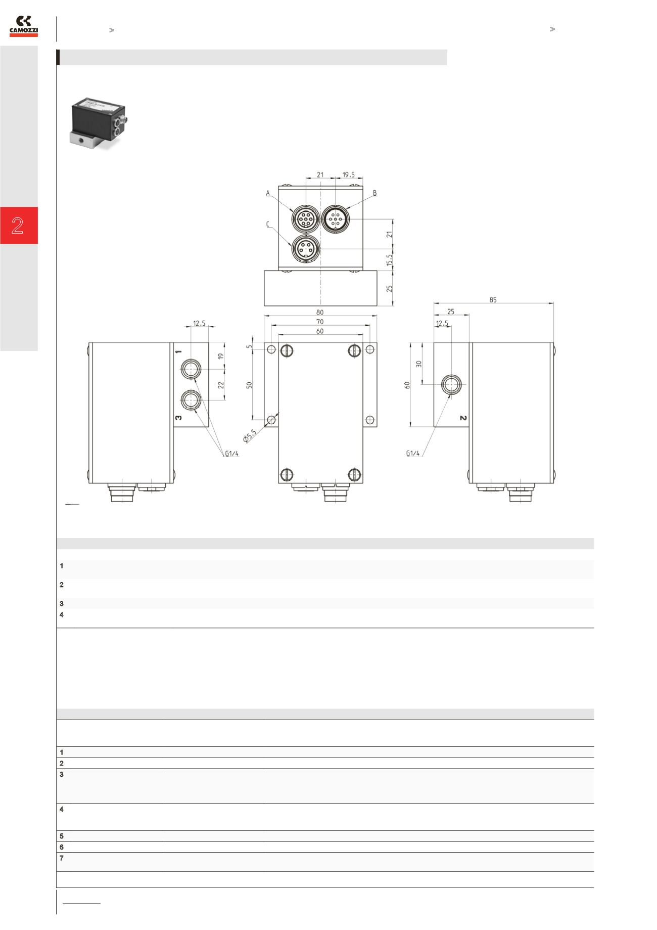
CONNECTORS M16 7 POLES
PIN FEMALE CONNECTOR M16
7 FOR SLAVE VALVE
MALE CONNECTOR M16 7
POLES FOR MASTER VALVE
SUPPLY
NOTES
1
Power supply +24 VDC
Power supply +24 VDC
2
Power supply GND
Power supply GND
3 Input signal(for slave valve,
+/- 5V vs. pin 4)
Input signal (Setpoint)
The total range of this signal corresponds to the total electric range of the feedback system. The cylinder is
positioned always and immediately to the position according to this signal. Therefore this signal has to have a
high signal quality: if, for example, the feedback system has a length of 300 mm, a ripple of 10 mVpp on the
command signal will generate a positioning ripple of +/-0.3 mm !!
4 GND input signal (for slave
valve, don’t connect to other
GND!)
GND Input signal
Pin 4 and 2 should be connected. If that is not possible, the voltage between both GND’s may not increase +/- 5
V.
5
NC
GND output feedback signal
For slave-valve, 0-5V vs. pin 4
6
NC
Output In-position
24 VDC vs. pin 2
7
NC
Output feedback signal
0-10 VDC vs. pin2. The accuracy-fault of that signal is about 2% and there is an offset of approx. 150 mV. Don’t
use it for precise documentations
A = female connector M16 7 poles for slave valve
B = male connector M16 7 poles for master valve supply
C = female connector M16 4 poles for the feedback system (position sensor)
FEMALE CONNECTOR M16 4 POLES FOR THE FEEDBACK SYSTEM (POSITION SENSOR)
PIN
FUNCTION
NOTES
1
GND
Potentiometer GND. Never connect this pin to other GNDs. Because of technical reasons the voltage at this pin is about half of the power
supply voltage.
2
Input of the feedback signal
Potentiometer output. If there isn`t used a potentiometer as feedback system, the output signal of the feedback system has to be 0-5 VDC. The
signal must have a floating GND (see remark to pin 1).
3
Output supply
For potentiometer, +5 VDC vs. pin 1
4
Shielding
The cable to the feedback system has to be shielded. At the feedback system’s end of the cable the shielding must be connected to the metallic
housing of the feedback system, at the valve’s end pin 4 is connected internally to the valve housing.
SERVO VALVES LRXA4 - PNEUMATICAL INSTALLATION