
Products designed for industrial applications.
General terms and conditions for sale are available on
www.camozzi.com.Series 45 guide units
CATALOGUE
1
/1.35.06
1
>
Release 8.8
MOVEMENT >
MOVEMENT
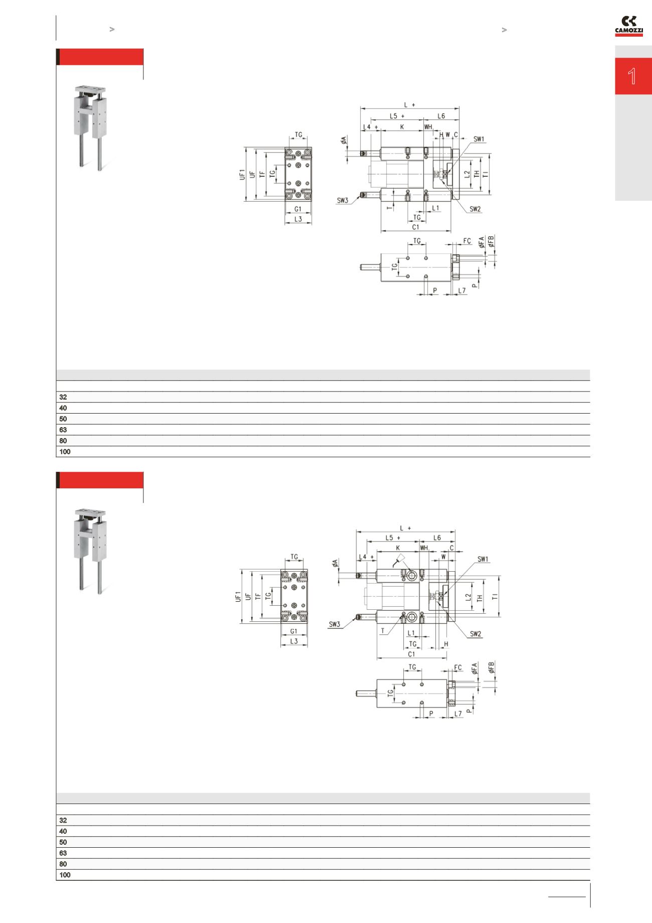
Guides Mod. 45NHT
Suitable for cylinders Series 60, 61 and 62 DIN/ISO 6431, ø 32, 40, 50, 63, 80 and 100.
These guides do not need lubrication. For applicable loads, see graph No. 3.
DIMENSIONS
Ø TF TG TH TI
UF G1 UF1
Ø
A WH C1 H W C K L L1 L2 L3 L4 L5 L6 L7 P T
Ø
FA
Ø
FB FC SW1 SW2 SW3
32 78 32.5 61 74 90 45 97 12 17 125 6 17 12 76 177 4.3 50.2 50 37 94 64 3 M6 14 6.5 11 6.8 13 17 6
40 84 38 69 87 110 54 115 16 21 140 7 22 12 81 192 11 58.2 58 37 105 74 3 M6 14 6.5 11 6.8 15 19 6
50 100 46.5 85 104 130 63 137 20 26 149 8 26 15 78.5 205 19.8 70.2 70 37.5 106 89 3 M8 16 9 15 9 22 24 6
63 105 56.5 100 119 145 80 152 20 26 178 8 26 15 111 237 15.3 85.2 85 37 121 89 7 M8 16 9 15 9 22 24 6
80 130 72 130 148 180 100 189 25 34 195 9 32 20 128 280 21 105.4 105 42 128 110 23 M10 20 11 18 11 27 30 6
100 150 89 150 172 200 120 213 25 39 220 9 32 20 128 280 24.5 130.4 130 37 138 115 3 M10 20 11 18 11 27 30 6
Supplied with:
4x fixing screws.
Draw note:
+ = add the stroke
Guides Mod. 45NHB
Suitable for cylinders Series 60, 61 and 62 DIN/ISO 6431, ø 32, 40, 50, 63, 80 and 100.
To lubricate these guides, use the special lubricator. For applicable loads, see graph No. 2.
DIMENSIONS
Ø TF TG TH TI
UF G1 UF1
Ø
A WH C1 H W C K L L1 L2 L3 L4 L5 L6 L7 P T
Ø
FA
Ø
FB FC SW1 SW2 SW3
32 78 32.5 61 74 90 45 97 12 17 125 6 17 12 76 177 4.3 50.2 50 37 94 64 3 M6 14 6.5 11 6.8 13 17 6
40 84 38 69 87 110 54 115 16 21 140 7 22 12 81 192 11 58.2 58 37 105 74 3 M6 14 6.5 11 6.8 15 19 6
50 100 46.5 85 104 130 63 137 20 26 149 8 26 15 78,5 237 19.8 70.2 70 69.5 106 89 3 M8 16 9 15 9 22 24 6
63 105 56.5 100 119 145 80 152 20 26 178 8 26 15 111 237 15.3 85.2 85 37 121 89 7 M8 16 9 15 9 22 24 6
80 130 72 130 148 180 100 189 25 34 195 9 32 20 128 280 21 105.4 105 42 128 110 23 M10 20 11 18 11 27 30 6
100 150 89 150 172 200 120 213 25 39 220 9 32 20 128 280 24.5 130.4 130 37 138 115 3 M10 20 11 18 11 27 30 6
Supplied with:
4x fixing screws.
Draw note:
+ = add the stroke


