
Products designed for industrial applications.
General terms and conditions for sale are available on
www.camozzi.com.Series 45 guide units
CATALOGUE
1
/1.35.02
1
>
Release 8.8
MOVEMENT >
MOVEMENT
CODING EXAMPLE
45
SERIES
N
VERSION
N = standard
UT
OPERATION
UT = “U” self lubricating guide
HT = “H” self lubricating guide
HB = “H” ball guide
050
BORE
016 = Ø 12-16 mm (available only in the UT version with “U” self lubricating guide)
020 = 20 mm
025 = 25 mm
032 = 32 mm
040 = 40 mm
050 = 50 mm
063 = 63 mm
080 = 80 mm
100 = 100 mm
A
MATERIALS
A = anodized aluminium body - stainless steel AISI 420B columns for 45UT and 45HT - hardened steel C50 columns for 45HB
0100
STROKE in mm
45
N
UT
050
A
0100
6512
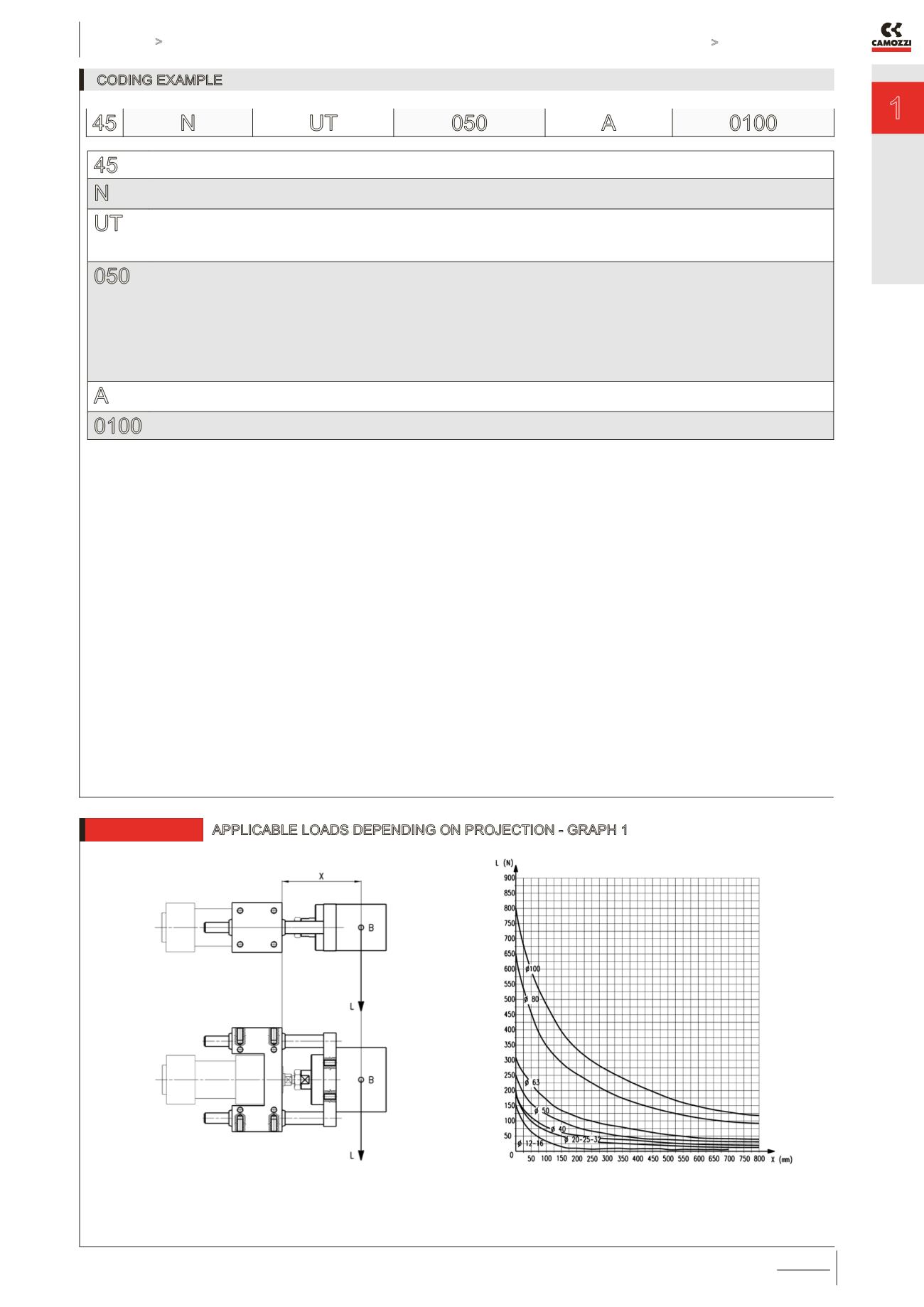
APPLICABLE LOADS DEPENDING ON PROJECTION - GRAPH 1
B = centre of gravity for applied load
L = load
X = fixed projection + stroke
fixed projection = distance to the centre of gravity
Guide “U” moving on bush (45NUT)


