
Products designed for industrial applications.
General terms and conditions for sale are available on
www.camozzi.com.1
Series 50 cylinders
MOVEMENT >
CATALOGUE
>
Release 8.8
/8.05.02
1
MOVEMENT
CODING EXAMPLE
50
SERIES
M
VERSION
M = standard magnetic
2
OPERATION
2 = double-acting cushioned
PNEUMATIC SYMBOL
CDSS (see the following pages)
P
MATERIALS
P = anodized AL profile tube - PU and NBR seals - standard carriage
U = anodized AL profile tube - PU and NBR seals - flanged carriage
50
BORE
16 = 16 mm
25 = 25 mm
32 = 32 mm
40 = 40 mm
50 = 50 mm
63 = 63 mm
80 = 80 mm
A
TYPE OF MOUNTING
A = standard
0500
STROKE (see table)
50 M
2
P
50
A
0500
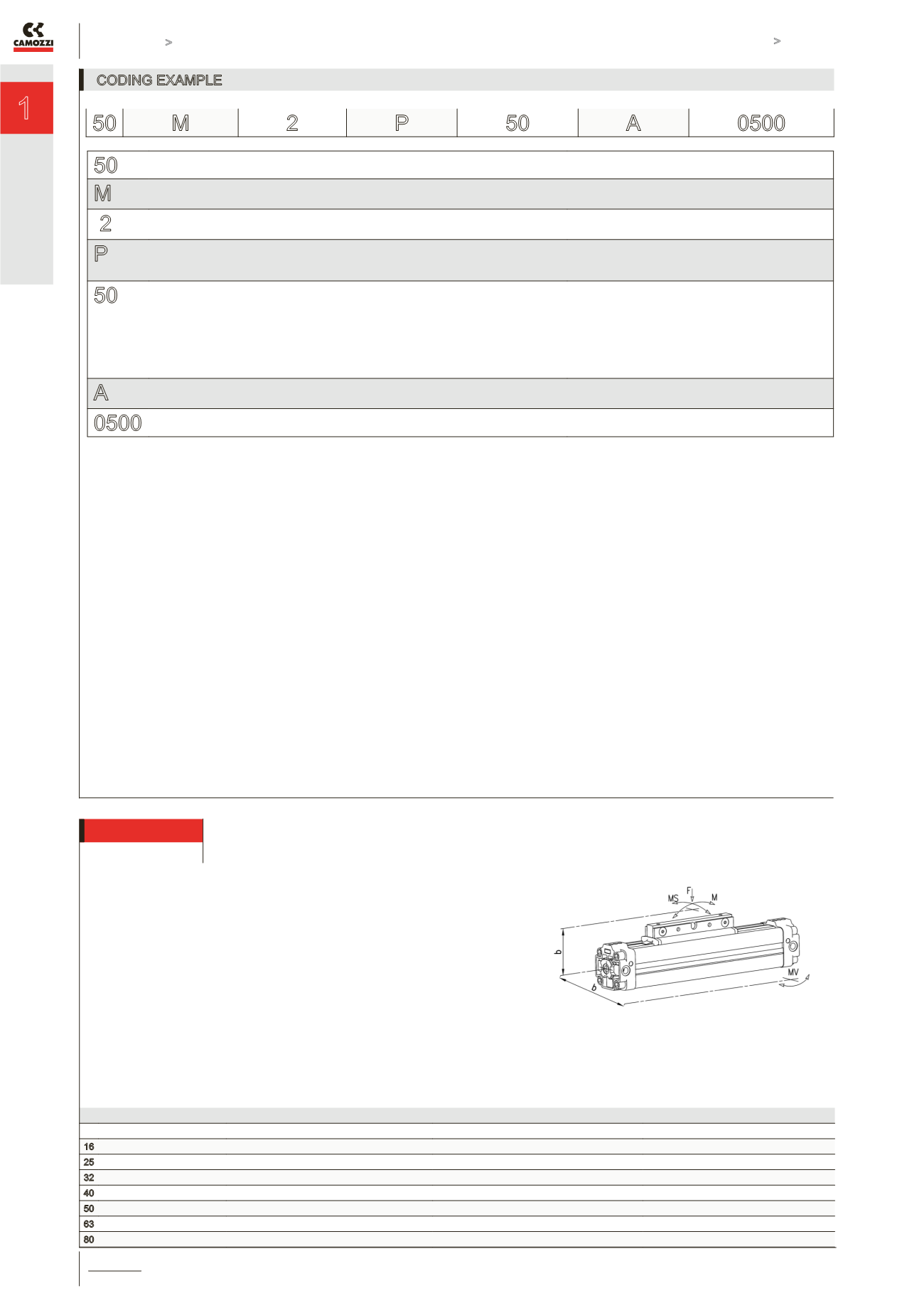
Ø Max. load permitted (N) F Max. bending torque force permitted (Nm) M Max. bending torque force permitted (Nm) Ms Torsional torque force permitted (Nm) Mv
16
218
3,1
0,5
1
25
660
12,4
1,9
5
32
720
30
4
8
40
1370
39
4
9
50
1600
122
11
16
63
2210
190
19
26
80
3770
305
30
47
MAXIMUM PERMITTED LOADS AND TORQUE FORCES
M = F x b
MS = F x b
MV = F x b
Note: Loads and bending torque are valid if applied
separately.


