
Products designed for industrial applications.
General terms and conditions for sale are available on
www.camozzi.com.Series 52 cylinders
CATALOGUE
1
/8.10.01
1
>
Release 8.8
MOVEMENT >
MOVEMENT
Series 52
rodless cylinders
Double-acting, magnetic, cushioned
ø 25, 32, 40, 50, 63 mm
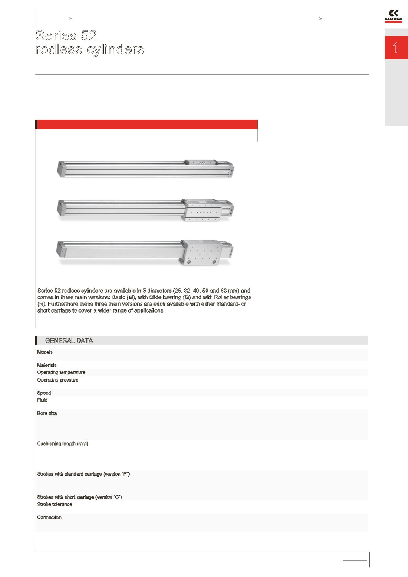
Series 52 rodless cylinders are available in 5 diameters (25, 32, 40, 50 and 63 mm) and
comes in three main versions: Basic (M), with Slide bearing (G) and with Roller bearings
(R). Furthermore these three main versions are each available with either standard- or
short carriage to cover a wider range of applications.
A permanent magnet is assembled on the
piston allowing the position to be detected
by means of proximity switches positioned
in grooves located on 3 sides on the
cylinder profile. The cylinder is equipped
with an end stroke cushioning which can
be regulated by means of a screw located
on each end cover of the cylinder. These
cylinders are also available in versions with
air supply from one side (end cover) only if
needed.
»
»
Three main versions,
Basic, Slide bearing
and Roller bearing
»
»
Extra short carriage as
option for all versions
»
»
Possibility of feeding both
chambers from one side only
GENERAL DATA
Models
Standard, with slide bearings, with roller bearings, air supply from one or both sides, with standard or short
carriage. For sizes 50 - 63 roller bearings version is not available.
Materials
AL (anodized), plastic, hardened steel, seals: NBR, PU
Operating temperature
- 10°C ÷ + 70 °C
Operating pressure
1 ÷ 8 bar
1,5 ÷ 8 bar ( Ø 25 for “R” version )
Speed
10 ÷ 1000 mm/sec (without load)
Fluid
filtered air, without lubrication. If lubricated air is used, it is recommended to use ISO VG32 oil. Once applied
the lubrication should never be interrupted. If speeds exceed 1 m/s lubricated air is recommended.
Bore size
Ø 25
Ø 32
Ø 40
Ø 50
Ø 63
Cushioning length (mm)
14 mm - Ø 25
20 mm - Ø 32
25 mm - Ø 40
22 mm - Ø 50
32 mm - Ø 63
Strokes with standard carriage (version “P”)
Strokes with short carriage (version “C”)
max 6000 mm - Ø25
max 5950 mm - Ø32
max 5900 mm - Ø40, Ø50
max 5880 mm - Ø63
max 6000 mm
Stroke tolerance
strokes ≤ 1000 mm = 0 / +0,6 mm
strokes > 1000 mm = 0 / +3 mm
Connection
G1/8 (Ø 25; 32)
G1/4 (Ø 40)
G3/8 (Ø 50; 63)


