
Products designed for industrial applications.
General terms and conditions for sale are available on
www.camozzi.com.Series CST-CSV-CSH-CSB-CSC-CSD sensors
CATALOGUE
1
/9.05.17
1
>
Release 8.8
MOVEMENT >
MOVEMENT
CONTACT STROKE AND HYSTERESIS - correct use of magnetic sensors
The magnetic sensors consist of a reed switch which is contained in a glass bulb
filled with a rarefied gas. The switches (or contacts) that are made of magnetic
material (nickel-iron) are flexible and are coated, at the contact points, with high
quality non-arcing materials. Switching is effected by means of a suitable magnetic
field and actuation is achieved by means of the permanent magnet
inside the piston.
NOTE: THE PRESENCE OF IRON MASSES NEAR THE CYLINDER OR THE
GRIPPERS (LIKE IRON SCREWS AND FIXING PLATES) CAN CHANGE THE
DIRECTION AND THE POWER OF THE MAGNETIC FIELD.
The Reed sensors are Normally Open, therefore, when subjected to the effect of the
magnetic field, close the circuit.
Series
Ø
b ( mm )
H ( mm )
24-25
16
9.2
1.2
24-25
20
12
1
24-25
25
11.7
1.1
27
20
10.5
1.6
27
25
10.9
1.6
27
32
10.7
1.1
27
40
12.1
1.7
27
50
12.1
1.2
27
63
14.1
1.3
QP
12
10
1.3
QP
16
11.8
1.5
QP
20
11.1
1.6
QP
25
10.6
1.6
QP
32
12.7
1.2
QP
40
12.5
1.1
QP
50
15.4
1.6
QP
63
16.7
1.5
QP
80
13.2
1.7
QP
100
16.8
1.8
31-32-ST 12
9.2
1.4
31-32-ST 16
7.9
1.3
31-32-ST 20
9.1
1.5
31-32-ST 25
10.6
1.5
31-32-ST 32
11.9
1.7
31-32-ST 40
12.9
2.2
31-32-ST 50
14.7
1.2
31-32-ST 63
15.2
1.4
31-32-ST 80
16.6
1.8
31-32-ST 100
16,8
1,7
40
160
24
2
40
200
26
2
Series
Ø
b ( mm )
H ( mm )
60
32
9.9
1
60
40
8.9
1.2
60
50
10.7
1
60
63
12.9
1.2
60
80
11.5
1.4
60
100
14.9
1.4
60
125
22
1
61
32
9
1
61
40
9.3
1.3
61
50
11
1.6
61
63
13.4
1.3
61
80
13.2
1.6
61
100
15.2
1.7
61
125
22.1
1.3
42
32
10.8
1.5
42
40
11.2
1.6
42
50
12.6
1.7
42
63
14.1
1.7
QCT
20
10
1.7
QCT
25
11.4
1.8
QCT
32
12.1
1.8
QCT
40
12.4
1.8
QCT
50
13.7
1.9
QCT
63
13.5
1.8
69
32
34.5
3.8
69
40
29.6
4.1
69
50
31.5
4.6
69
63
32.3
3.1
69
80
24
2.9
69
100
25.6
2.9
69
125
30.1
1.7
Series
Ø
b ( mm )
H ( mm )
62-63-6PF 32
10
1
62-63-6PF 40
11
1
62-63-6PF 50
12
1.2
62-63-6PF 63
13
1
62-63-6PF 80
13
1
62-63-6PF 100
16
1
52
25
19.3
1.8
52
32
27.9
1.6
52
40
26
2.3
52
50
39.9
2.9
52
63
40.7
4.2
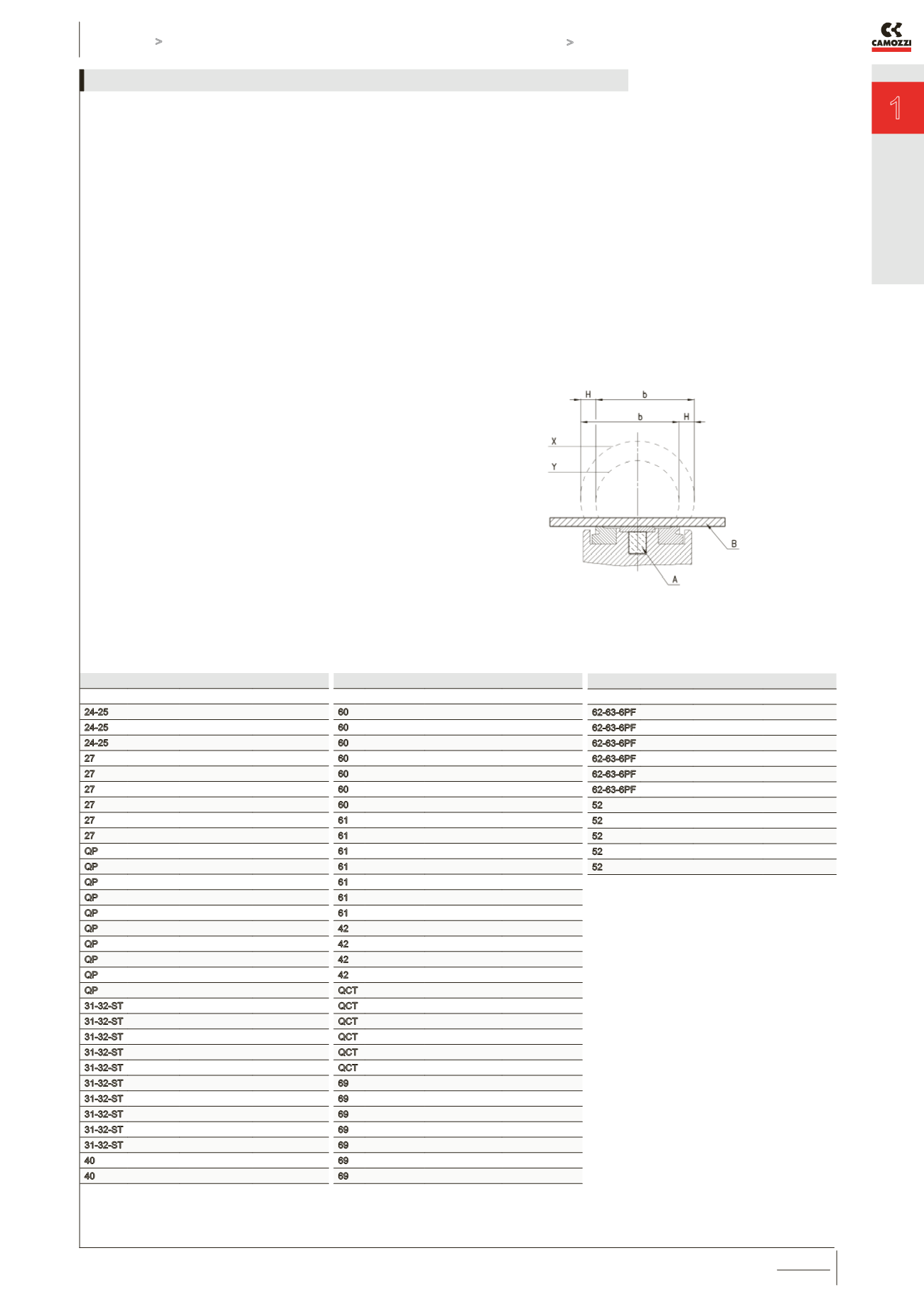
OPERATING FIELD OF SENSORS
WITH RESPECT TO THE MAGNETIC PISTON (below picture)
The maximum speed (in m/second) for a cylinder guided by magnetic sensors is given
by b/t = speed where:
b = contact stroke in mm (see the table) - this value indicates the amplitude of
the magnetic field or switching field when the circuit is closed.
t = total reaction time in milliseconds of the electric control components
connected downstream of the sensor
H = operational hysteresis of the sensor with respect to the shape and amplitude
of the magnetic field.
A = magnet
B = actuator
X =
Y =
The operating field, as a result of hysteresis, is displaced by the value H in the
opposite direction to movement of the cylinder. The maximum speed permitted for
each cylinder depends on value b and on reaction time of the different components
connected downstream of the sensor.


