


 378 / 1278

Products designed for industrial applications.
General terms and conditions for sale are available on
www.camozzi.com.Series CSN proximity switches
CATALOGUE
1
/9.10.02
1
>
Release 8.8
MOVEMENT >
MOVEMENT
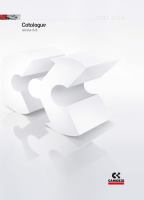
CONNECTION
- For inductive loads = solenoid valves, electrical magnets,
relay.
To connectors = terminals 1 - 2
- For capacitive loads = circuit with remaining tension (see PLC
controls)
To connectors = 1 - 3
Note: For connections with wires of approximately 10m, the
connection shall be made as for a capacitive load.
MAXIMUM LOADS
For maximum loads see relative diagram, those loads are valid
only for inductive loads. For capacitive loads, using clamp 3
(or black wire) load must not exceed 80 mA and load must be
given by PLC or, for electrical circuits, by microrelay or micro
solenoid valves with 2W maximum consumption.
Note: When operating with direct current, clamp 1 must
always be connected to the positive outlet (+). In cases where
commands are given from the PLC and logic NPN, clamp 1
must be connected to the inlet. In cases where commands
are given from the PLC and logic PNP, clamps 2 or 3 must be
connected to the inlet.
LEGEND:
C1 = capacitive load
C2 = inductive load
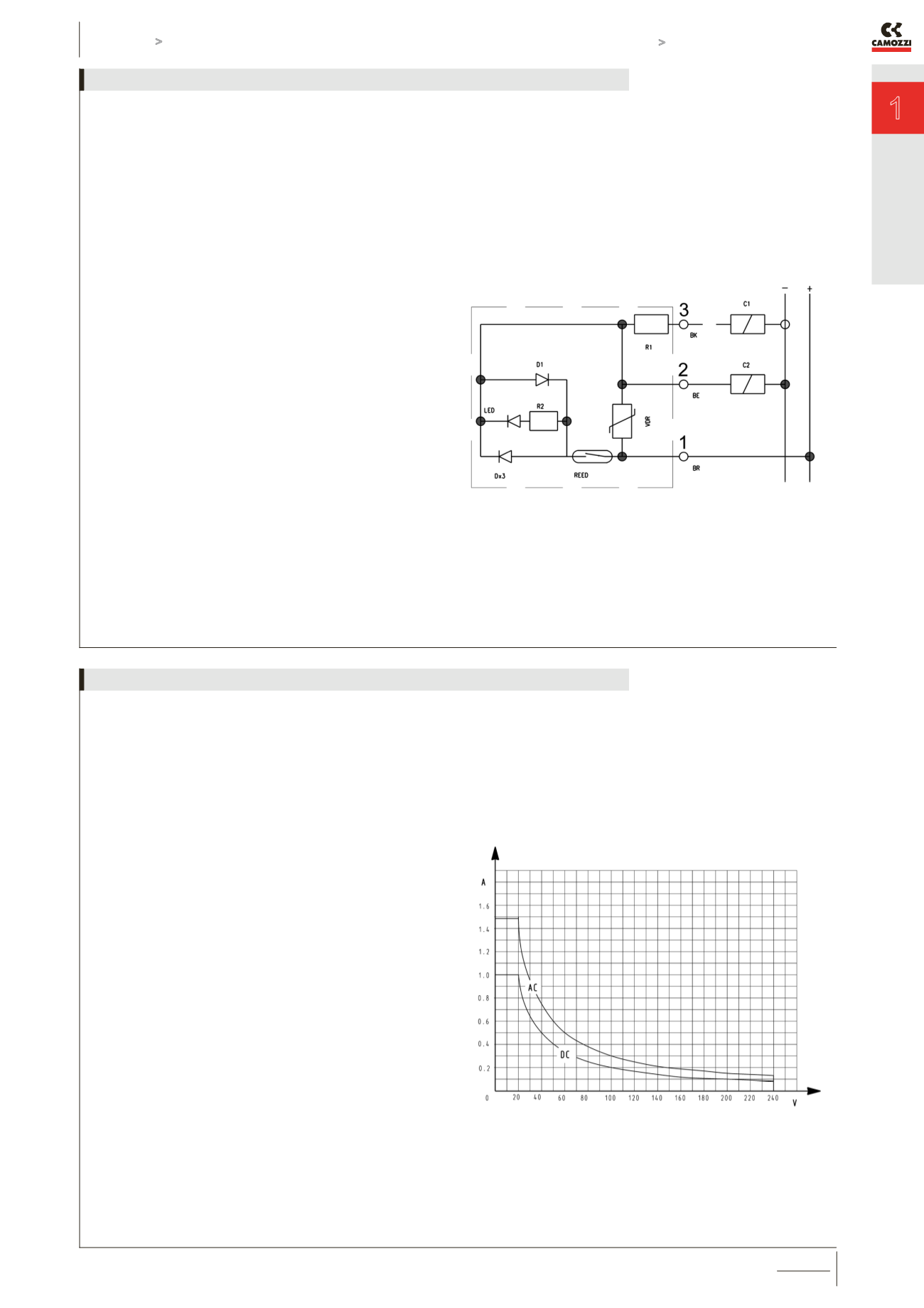
TECHNICAL DATA
The maximum load (W) which the contacts are able to tolerate
is that indicated in the section “General data”, i.e.
- 20 W for direct current ( DC )
- 30 VA for alternating current ( AC )
The effective load allowed depends on the operating voltage
(minimum 12 V, maximum 220 V) as shown in the following
graph.
Note: this graph was obtained from practical tests performed
using a load consisting of our Series A and 6 solenoid valves,
at an operating speed of one stroke per second.
For higher operating speeds, your are advised to contact our
technical department.
Maximum contact load