
Products designed for industrial applications.
General terms and conditions for sale are available on
www.camozzi.com.2
Series 130 electronic control device
CONTROL >
CATALOGUE
>
Release 8.8
/15.03.02
2
CONTROL
CODING EXAMPLE
130
SERIES
2
VOLTAGE:
2 = 24 V DC (max power 24 W)
3 = 12 V DC (max power 12 W)
4 = 6 V DC (max power 6 W)
5 = 11 V DC (max power 11 W)
2
POWER:
1 = 3 W
2 = 6.5 W
3 = 3.2 W
4 = 4.3 W
5 = 10 W
2
PWM FREQUENCY:
2 = 500 Hz
3 = 1 KHz
NOTE: it is possible to realize configurations with voltage, power and PWM frequency values that are not yet foreseen in the coding example.
For further information we suggest you to contact our technical department.
130
-
2
2
2
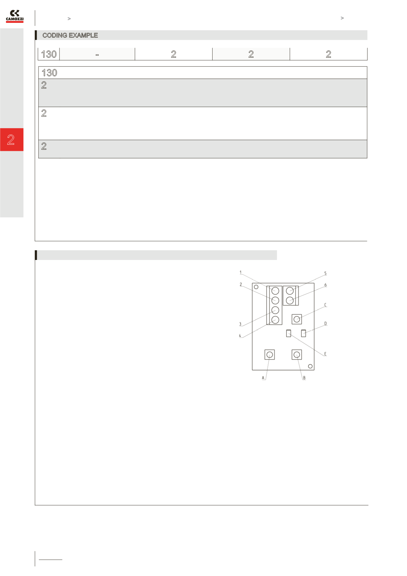
DRAWING LEGEND:
1 = 6 ÷ 24 V DC (supply)
2 = 0 V (Ground) common also for the reference signal
3 = analogical reference signal 0 ÷ 10V DC
4 = analogical reference signal 4 ÷ 20 mA
A = regulation of min. current (OFFSET)
B = regulation of max. current (SPAN)
C = regulation of the PWM outlet up and down ramp
D = red LED
E = yellow LED
Note 1: the GND of the reference signal and the GND of supply
have to be linked together.
Note 2: For the valve connection use a connector without
protection - diodes, varistors, etc... - as these might alter the
regulation of the device.
ELECTRICAL CONNECTIONS AND SETTINGS


