
Products designed for industrial applications.
General terms and conditions for sale are available on
www.camozzi.com.Series LR digital proportional servo valves
CATALOGUE
2
/15.32.02
2
>
Release 8.8
CONTROL >
CONTROL
CODING EXAMPLE
L
SERIES:
L = proportional servo valves
R
TECHNOLOGY:
R = rotating spool
W
VERSION:
W = flow control
P = pressure control
X = position control
D
ELECTRONICS:
D = digital
2
MODEL:
2 = compact DIN-RAIL
3
FUNCTION:
3 = 3/3-way
4
NOMINAL DIAMETER:
4 = 4 mm
6 = 6 mm
1
COMMAND SIGNAL (Setpoint):
1 = +/- 10 V
2 = 0 - 10 V
4 = 4 - 20 mA
A
INPUT SIGNAL:
2 = 0 - 10 V (LRPD2 and LRXD2 only)
4 = 0 - 5V (LRPD2 and LRXD2 only)
5 = 4 - 20mA (LRPD2 and LRXD2 only)
A = internal encoder (LRWD2 only)
B = 1 bar (internal sensor - LRPD2 only)
D = 10 bar (internal sensor - LRPD2 only)
E = 250 mbar (internal sensor - LRPD2 only)
F = +1/-1 bar (internal sensor - LRPD2 only)
00
CABLE:
00 = no cable
2F = straight cable of 2 m
2R = 90° cable of 2 m
5F = straight cable of 5 m
5R = 90° cable of 5 m
L R W D 2 -
3 4 -
1 -
A -
00
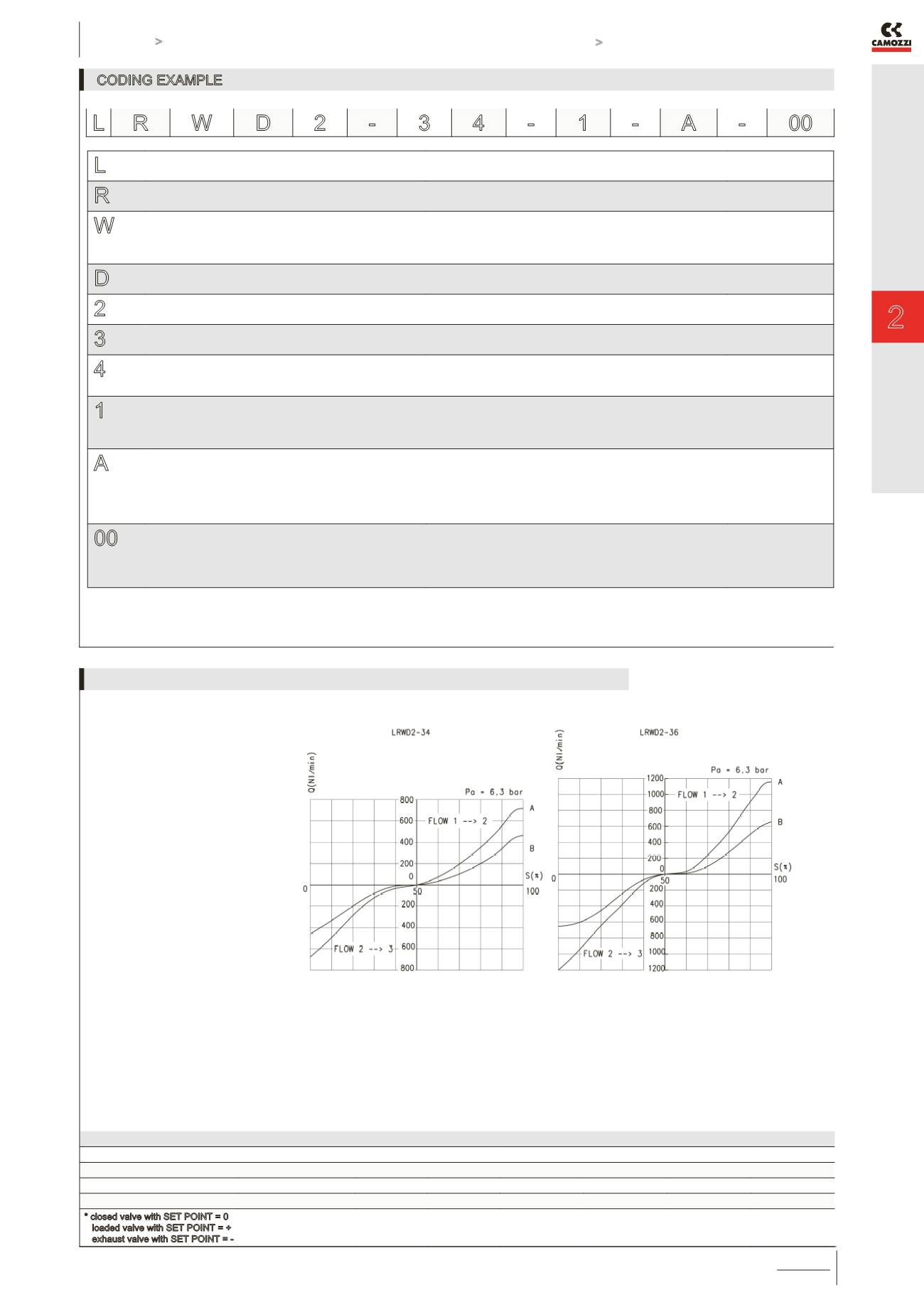
LEGEND:
A = free flow
B = ∆P1
Q = flow (Nl/min)
S = set point (%)
Pa = inlet pressure (bar)
RESPONSE TIMES ACCORDING TO THE COMMAND SIGNAL IN COMPLIANCE WITH THE ISO 10094-2 STANDARD
COMMAND SIGNAL
-5% ÷ +5% +5% ÷ -5% -25% ÷ +25% +25% ÷ -25% -90% ÷ +90% +90% ÷ -90%
Time [ms] LRWD2-34
4
5
6
9
10
10
Time [ms] LRWD2-36
5
5
6
6
10
10
* closed valve with SET POINT = 0
loaded valve with SET POINT = +
exhaust valve with SET POINT = -
FLOW DIAGRAMS FOR VALVES LRWD2-34 AND LRWD2-36


