
Products designed for industrial applications.
General terms and conditions for sale are available on
www.camozzi.com.Series ER100 digital electro-pneumatic regulators
CATALOGUE
2
/15.50.03
2
>
Release 8.8
CONTROL >
CONTROL
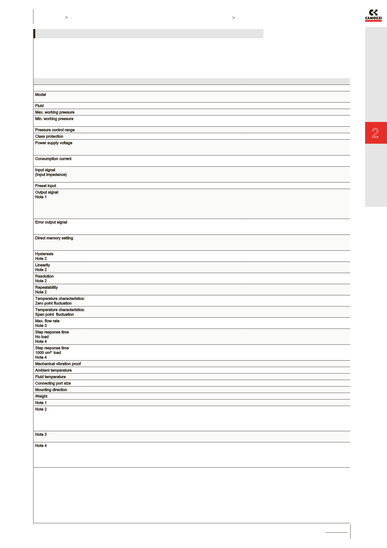
Model
ER104-9 0/1/2 X
Analog type
ER104-9P X
Parellel type
Fluid
Filtered air according to ISO 132
Filtered air according to ISO 132
Max. working pressure
10 bar
10 bar
Min. working pressure
Control pressure +
Max. control pressure + 1 bar
Control pressure +
Max. control pressure + 1 bar
Pressure control range
0,5 ÷ 9 bar
0,5 ÷ 9 bar
Class protection
IP40
IP40
Power supply voltage
DC24V ± 10%
(stabilized power supply
with a ripple rate of 1% or less)
DC24V ± 10%
(stabilized power supply
with a ripple rate of 1% or less)
Consumption current
0.15 A or less rush current 0.6 A
or less when power is turned on
0.15 A or less rush current 0.6 A
or less when power is turned on
Input signal
(Input impedance)
0 a 10 VDC (6.7kΩ)
0 a 5 VDC (10kΩ)
4 a 20 mADC (250 Ω)
10 bit
Preset input
8 points
N/A
Output signal
Note 1
Analog output 1-5 VDC (load to be connected
impedance 500 KW or more )
Switch output NPN or PNP, open collector output,
30 V or less, 50 mA or less
voltage drop 2.4.V or less, compatible for
usage in PLC and Relay.
Analog output 1-5 VDC (load to be connected
impedance 500 KW or more )
Switch output NPN or PNP, open collector output,
30 V or less, 50 mA or less,
voltage drop 2.4.V or less, compatible for usage
in PLC and Relay.
Error output signal
NPN or PNP, open collector output,
30 V or less, 50 mA or less, voltage drop 2.4 or less,
compatible for usage in PLC and Relay
NPN or PNP, open collector output,
30 V or less, 50 mA or less, voltage drop 2.4 or less,
compatible for usage in PLC and Relay
Direct memory setting
0,05 ÷ 9 bar
minimum input width 0,01 bar
setting resolution 0,02 bar
0,05 ÷ 9 bar
minimum input width 0,01 bar
setting resolution 0,02 bar
Hysteresis
Note 2
0.5% F.S. or less
0.5% F.S. or less
Linearity
Note 2
±0.3% F.S. or less
±0.3% F.S. or less
Resolution
Note 2
0.2% F.S. or less
0.2% F.S. or less
Repeatability
Note 2
0.3% F.S. or less
0.3% F.S. or less
Temperature characteristics:
Zero point fluctuation
0.15% F.S./°C or less
0.15% F.S./°C or less
Temperature characteristics:
Span point fluctuation
0.07% F.S./°C or less
0.07% F.S./°C or less
Max. flow rate
Note 3
400 l/min (see diagram)
400 l/min (see diagram)
Step response time
No load
Note 4
0.82 sec. or less
0.2 sec. or less
Step response time
1000 cm³ load
Note 4
0.8 sec. or less
0.8 sec. or less
Mechanical vibration proof
98 m/s² or less
98 m/s² or less
Ambient temperature
5°C ÷ 50 °C
5°C ÷ 50 °C
Fluid temperature
5°C ÷ 50 °C
5°C ÷ 50 °C
Connecting port size
G1/4
G1/4
Mounting direction
Free
Free
Weight
250g
250g
Note 1
Select either analog or switch output.
Note 2
This characteristic is guaranteed within a regulation range between 10 and 90% of the full
scale, with a power voltage of 24V±10%, a supply pressure of 1 bar higher compared with
the set pressure (ex. regulation of 3 bar, supply pressure of 3+1 = 4 bar) and a volume
connected to the outlet without any loss. In applications with great air consumption, such as
the blowing, the indicated tolerance may change.
Note 3
The above apply when working pressure
and control pressure are maximum.
Note 4
The above apply when working pressure and control pressure is maximum
and the step is as follows:
50% F.S. -> 100%F.S.
50% F.S. -> 60% F.S.
50% F.S. -> 40% F.S.
GENERAL DATA ER104-9xxx


