


 156 / 210

145
3
SHORT FORM CATALOGUE
>
Release 8.8
3
TREATMENT
Products designed for industrial applications.
General terms and conditions for sale are available on
www.camozzi.com.TREATMENT >
Series MX
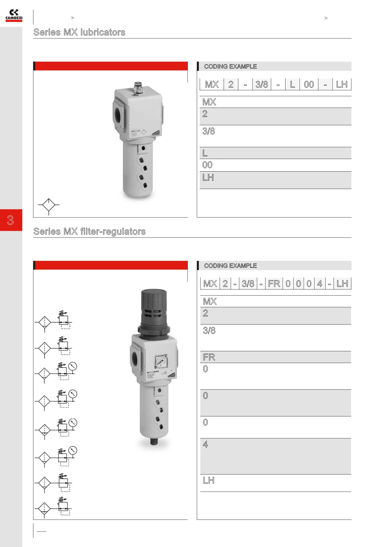
Series MX lubricators
MX2 ports: G3/8, G1/2, G3/4 - MX3 ports: G3/4, G1
Modular
Bowl with technopolymer cover and bayonet-type mounting
CODING EXAMPLE
MX 2 - 3/8 - L 00 - LH
Series MX filter-regulators
MX2 ports: G3/8, G1/2, G3/4 - MX3 ports: G3/4, G1
Modular
Bowl with technopolymer cover and bayonet-type mounting
CODING EXAMPLE
MX 2 - 3/8 - FR 0 0 0 4 - LH
LU01 =
lubricator
* = Further details about condensate drains are available at the end of this chapter
MX
SERIES
2
SIZE:
2 = G3/8 - G1/2 - G3/4
3 = G3/4 - G1
3/8
PORT:
1/2 = G1/2
3/4 = G3/4
1 = G1
L
LUBRICATOR
00
DESIGN TYPE:
00 = atomized oil
LH
FLOW DIRECTION:
= from left to right (standard)
LH = from right to left
MX
SERIES
2
SIZE:
2 = G3/8 - G1/2 - G3/4
3 = G3/4 - G1
3/8
PORT:
3/8 = G3/8
1/2 = G1/2
3/4 = G3/4
1 = G1
FR
FILTER-REGULATOR
0
FILTERING ELEMENT WITH DESIGN TYPE:
0 = 25 µm with relieving (standard)
1 = 5 µm with relieving
2 = 25 µm without relieving (with semiautomatic-manual drain only)
3 = 5 µm without relieving (with semiautomatic-manual drain only)
0
DRAINING OF CONDENSATE *:
0 = semiautomatic-manual drain (standard)
3 = automatic drain
5 = depressuring drain, protected
8 = without drain, with port G1/8
0
OPERATING PRESSURE:
0 = 0,5 ÷ 10 bar (standard)
4 = 0 ÷ 4 bar
7 = 0,5 ÷ 7 bar (MX2 only)
4
PRESSURE GAUGE:
0 = without pressure gauge(with threaded port)
2 = with built-in pressure gauge 0-6 and working pressure 0 ÷ 4 bar
3 = with built-in pressure gauge 0-10 and working pressure
0 ÷ 7 bar (MX2 only)
4 = with built-in pressure gauge 0-12 and working pressure
0,5 ÷ 10 bar (standard)
LH
FLOW DIRECTION:
= from left to right (standard)
LH = from right to left
FR01 =
filter-regulator
with relieving
and manual drain
FR02 =
filter-regulator
with relieving and
without drain
FR03 =
filter-regulator
with relieving,
manual drain and
pressure gauge
FR04 =
filter-regulator
with relieving,
without drain and
with pressure gauge
FR05 =
filter-regulator
with relieving,
automatic drain and
pressure gauge
FR10 =
filter-regulator
with manual drain,
without relieving and
with pressure gauge
FR11 =
filter-regulator
with manual drain and
wiithout relieving
FR18 =
filter-regulator
with relieving and
automatic drain