


 101 / 226

The company reserves the right to vary models and dimensions without notice.
These products are designed for industrial applications and are not suitable for sale to the general public.
91
a i r p i l o t v a l v e s
3
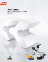
Dimensions in millimeters (mm)
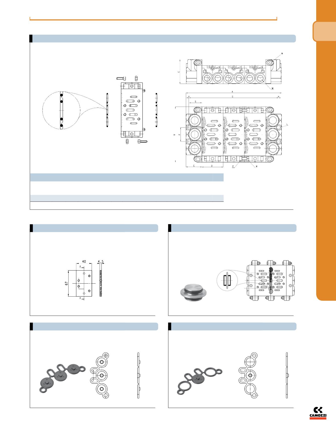
Cover plate for the positions which are not used.
Complete with seals and screws.
Separation tap lines 1/3/5 to be used with
manifold type 901C - 902C.
Mod.
901-C1A/TP
Size 1
Mod.
902-C2A/TP
Size 2
Separation joint to be used with
manifold type 901N.
P-R-S plugged.
Separation joint to be used with
manifold type 901N.
P plugged.
1 plugged
dimensions
NPTF
Size
A
B
C
D E
F
G
H L
M N
UNI 5931
P
UNI 5588
R
S
1
N° D+2E 110 48 43 32 28 n° D+2S 1 3.5 1/4 1/8 M5 x 14
M5 25.5
(ISO size 1 only)
(ISO size 1 only)
Assembly for front outlet manifold sub-bases: (shown with “N1A” & “HN1” assembly dimensions in mm units)
Mod. 901-TP (ISO size 1 only)
Example of assembly - blocking discs
Mod. 901-N1A/T - full blocking gasket
Mod. 901 - N1A/TP - pressure blocking gasket
1/3/5 plugged