
The company reserves the right to vary models and dimensions without notice.
These products are designed for industrial applications and are not suitable for sale to the general public.
89
a i r p i l o t v a l v e s
3
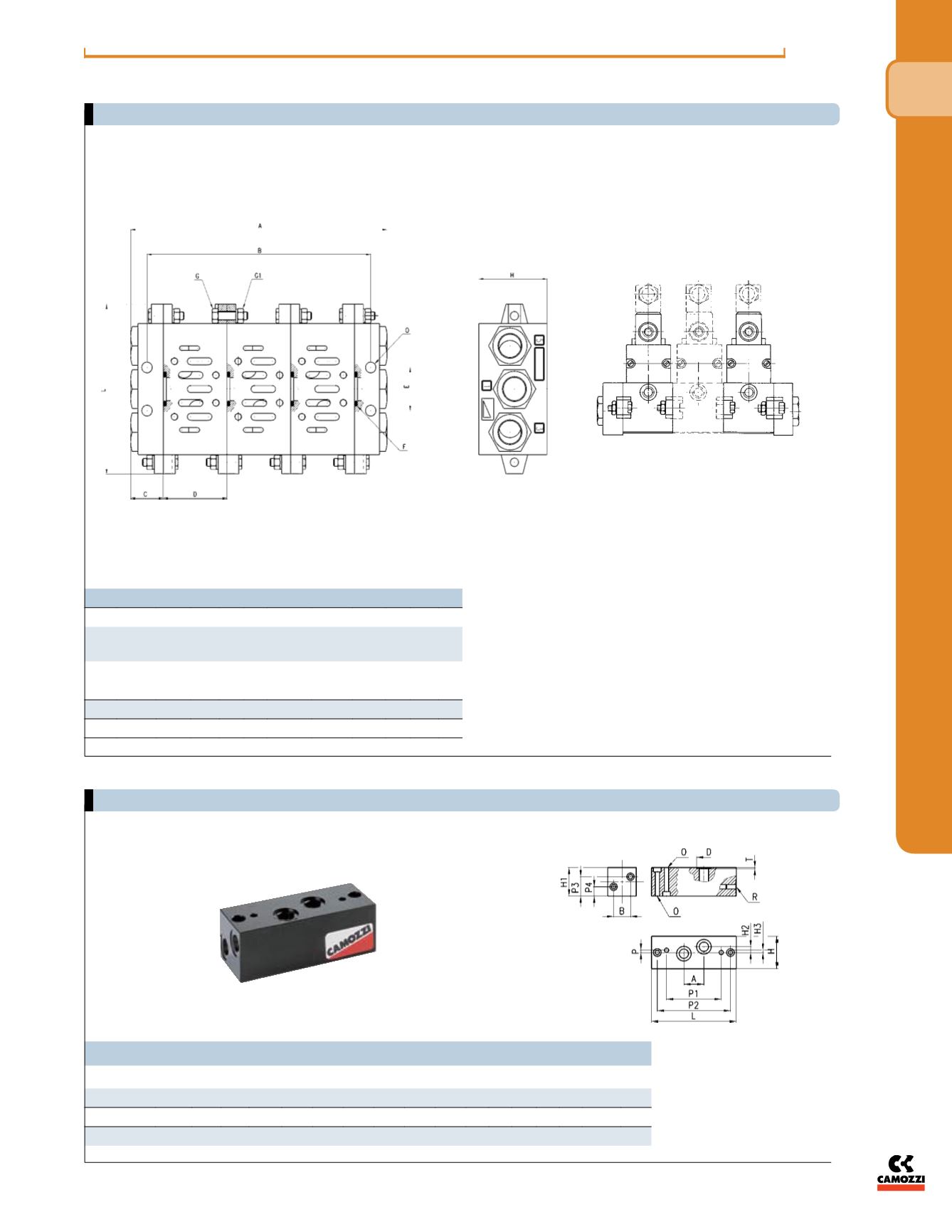
Dimensions in millimeters (mm)
DIMENSIONS
Size
A
B
C D E
F
G
G1 H L
O
O-Ring
Part No.
UNI
5739
UNI
5588
1
n°
D+2C
n°
D+C 22 43 28 3068 M5x20 M5 46 110 7
2 n° D+2C n° D+C 26 56 35 3093 M6x25 M6 47 135 9
3 n° D+2C n° D+C 30 71 52 4125 M8x25 M8 56 190 12
Note
: complete with fixing screws and O-ring.
(with “C” manifolds & “H” end-blocks)
Valves shown for illustration purposes only
Assembly of manifold sub-base (VDMA 24345) assembly dimensions for “C” manifold with “H” end plates
Manifold assembly with valves
Manifold segment adapter with front outlets (VDMA 24345): for use with“C” manifold to adapt to end outlets
dimensions
NPTF
Mod.
Size
A
B
D
H H1 H2 H3 L
O P P1 P2 P3 P4 R
T
901-N1 TF
1 26 22 19 42 37 7.5 1.5 110 5.5 3 71 95 25 12 1/4 1.4
902-N2 TF
2 30 29 23 55 40 6 5 135 6.5 3 86 115 26 14 3/8 1.4
903-N3 TF
3 38 36 27 70 45 8 6 190 9 3 130 168 29 17 1/2 1.4


