


 87 / 226

The company reserves the right to vary models and dimensions without notice.
These products are designed for industrial applications and are not suitable for sale to the general public.
77
a i r p i l o t v a l v e s
3
Dimensions in millimeters (mm)
Note
: complete with screws and seal.
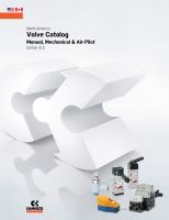
Supply unit for manifold bases, (for auxillary pressure supply or different pressure zones)
with common inlet and exhaust ports
Note
: complete with screws and seal.
Blocking Disc
CONTROL >
Electropneumatically and pneumatically operated valves Series 7
GENERAL CATALOGUE
>
Release 8.1
2
Diaphragm for manifold bases
Diaphragm for manifold bases with common inlet
and exhaust ports and with outlet ports on the front.
Mod.
701C - N1A - TP
702C - N2A - TP
Excluder tap for manifold bases
The following is supplied:
N° 1 seal
N° 2 screws
DIMENSIONS
Mod.
Size ISO
A
B
C
D
701-TP
26 mm
26,5
61,7
10
4,2
702-TP
18 mm
18,5
52,2
10
3,2
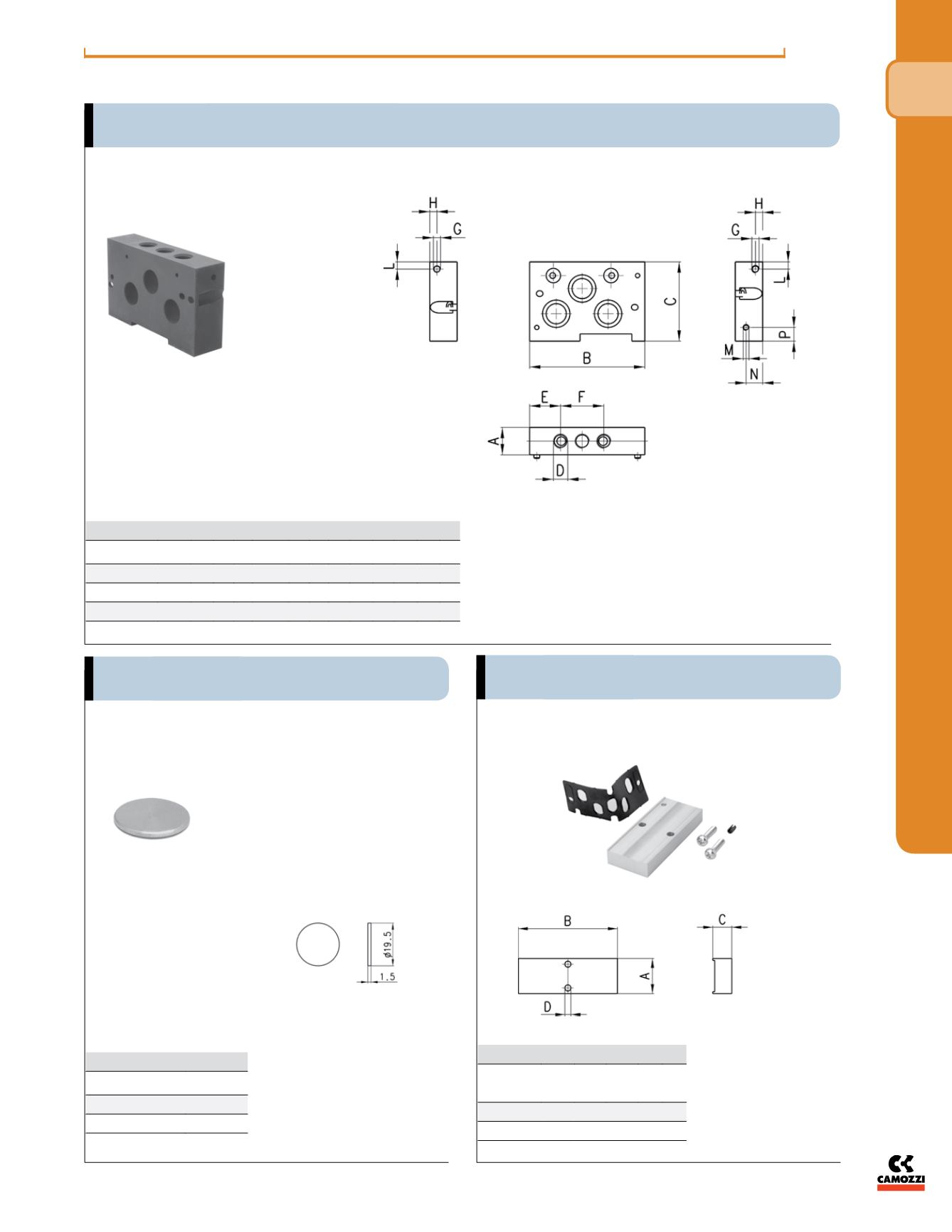
Interface between ISO 01 and ISO 02
Note: complete with screws and
seal.
CONTROL >
Electropneumatically and pneumatically operated valves Series 7
2
nifold bases
ifold bases with common inlet
nd with outlet ports on the front.
anifold bases
DIMENSIONS
NPTF
Mod.
Size ISO A B C
D E F G H L M N P
701C-N1NTF
26 mm 27 100 65 1/4 27 38 M5 6.5 10 M4 10 10
702C-N2NTF
18 mm 19 80 55 1/8 21.5 30 M5 5 5 M4 11.5 9.5
DIMENSIONS
Mod.
Size
ISO A
B C D
701-TP
26 mm 26.5 61.7 10 4.2
702-TP
18 mm 18.5 52.2 10 3.2
DIMENSIONS
Mod.
Size
701C-N1A-TP
01 (26 mm)
702C-N2A-TP
02 (18 mm)
Diaphragm for manifold bases with common inlet
and exhaust ports and with outlet ports on the front
Excluder tap - blanking plate
for manifold bases