
The company reserves the right to vary models and dimensions without notice.
These products are designed for industrial applications and are not suitable for sale to the general public.
73
a i r p i l o t v a l v e s
3
Dimensions in millimeters (mm)
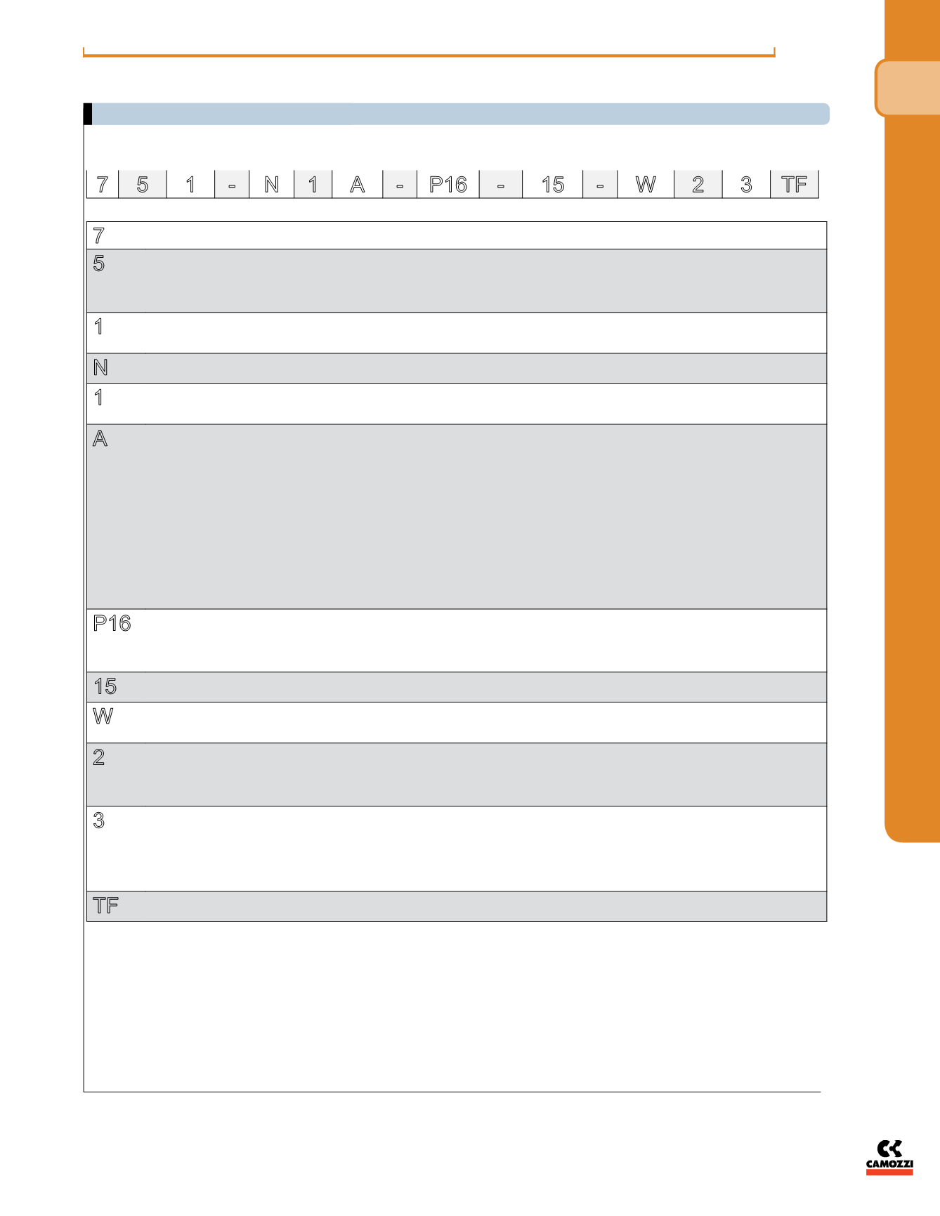
CODING OF VALVES AND SOLENOID VALVES SERIES 7 WITH SUB-BASES - (ORDERED SEPARATELY)
7
SERIES:
5
NUMBER OF WAYS - POSITIONS:
5 = 5/2
6 = 5/3 CC
7 = 5/3 CO
8 = 5/3 CP
1
SIZES:
1 = size 26 mm
2 = size 18 mm
N
SUBBASE:
N = sub-base with front outlets
1
PORTS:
1 = 1/4 NPTF (Size 26 mm)
2 = 1/8 NPTF (Size 18 mm)
A
NUMBER OF SUBBASES:
**A = 1
**B = 2
**C = 3
**D = 4
**E = 5
**F = 6
**G = 7
**H = 8
**K = 9
**L = 10
**M = 11
**N = 12
**P = 13
**R = 14
**S = 15
P16
ACTUATION:
33 = pneumatic, bistable
36 = pneumatic, monostable
P11 = electro-pneumatic, bistable
P16 = electro-pneumatic, monostable
15
SOLENOID INTERFACE:
15 = 15x15
W
SOLENOID TYPES:
W = Series W
*P = Series P
2
CONNECTION:
* 1 = wire 300 mm (series W)
2 = 2 pins (series W 24V - 48V DC/AC)
* 3 = 2 pins+earth (series W only 110V DC/AC)
* 5 = 2 pins+earth (series P)
3
SOLENOID VOLTAGE:
3 = 24V DC
* 4 = 48V DC
* 6 = 110V DC
* B = 24V 50/60 Hz
* C = 48V 50/60 Hz
* D = 110V 50/60 Hz
TF
TF = NPTF ports
blank = BSP ports
7 5 1 - N 1 A - P16 -
15 - W 2 3 TF


