


 546 / 1144

Products designed for industrial applications.
General terms and conditions for sale are available on
www.camozzi.com.2
Series 3 Plug-In valve islands
CONTROL >
CATALOGUE
>
Release 8.7
/3.05.03
2
CONTROL
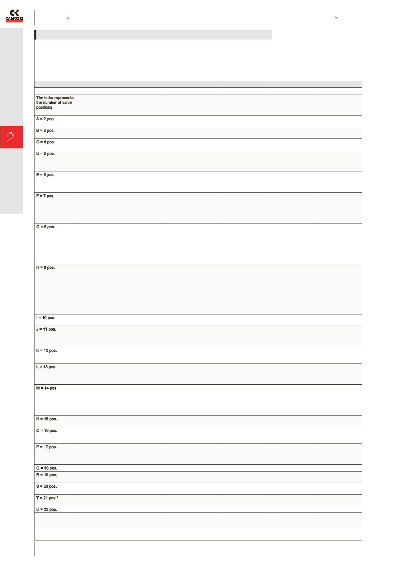
The letter represents
the number of valve
positions
Number of valve positions,
showing the combination
of the modules from which
the valve island is built.
Position of the D-SUB
and number of valves
to which it is connected.
[left]
Position of the D-SUB
and number of valves
to which it is connected.
[right]
Configuration code
Positions
Configuration code
A = 2 pos.
[2]
(2)
-
2
2
-
A
A
A - A
A - B
B = 3 pos.
[3]
(3)
-
3
3
-
B
B
A - A
A - B
C = 4 pos.
[2] [2]
(2) (2)
-
4
4
-
C
C
A - A
A - B
D = 5 pos.
[3] [2]
(3) (2)
[2] [3]
(2) (3)
-
5
-
5
5
-
5
-
D
D
D
D
A - A
A - B
A - C
A - D
E = 6 pos.
[3] [3]
(3) (3)
[2] [2] [2]
(2) (2) (2)
-
6
-
6
6
-
6
-
E
E
E
E
A - A
A - B
B - A
B - B
F = 7 pos.
[2] [3] [2]
(2)(3)(2)
[2] [2] [3]
(2) (2) (3)
[3] [2] [2]
(3) (2) (2)
-
7
-
7
-
7
7
-
7
-
7
-
F
F
F
F
F
F
A - A
A - B
B - A
B - B
B - C
B - D
G = 8 pos.
[3] [3] [2]
(3)(3)(2)
[2] [3] [3]
(2)(3)(3)
[2] [2] [2] [2]
(2)(2)(2) (2)
[3] [2] [3]
(3) (2) (3)
-
8
-
8
-
8
-
8
8
-
8
-
8
-
8
-
G
G
G
G
G
G
G
G
A - A
A - B
A - C
A - D
B - A
B - B
B - C
B - D
H = 9 pos.
[3] [3] [3]
(3)(3)(3)
[3] [2] [2] [2]
(3)(2)(2) (2)
[2] [3] [2] [2]
(2) (3) (2) (2)
[2] [2] [3] [2]
(2) (2) (3) (2)
[2] [2] [2] [3]
(2) (2) (2) (3)
-
9
-
9
-
9
-
9
-
9
9
-
9
-
9
-
9
-
9
-
H
H
H
H
H
H
H
H
H
H
A - A
A - B
B - A
B - B
B - C
B - D
B - E
B - F
B - G
B - H
I = 10 pos.
[2] [3] [3] [2]
(2)(3)(3)(2)
-
10
10
-
I
I
A - A
A - B
J = 11 pos.
[2] [3] [3] [3]
(2)(3)(3)(3)
[3] [3] [3] [2]
(3)(3)(3)(2)
-
11
-
11
11
-
11
-
J
J
J
J
A - A
A - B
A - C
A - D
K = 12 pos.
(3) [3] [3] [3]
(3)(3)[3] [3]
(3) (3)(3) [3]
3
6
9
9
6
3
K
K
K
A - A
A - B
A - C
L = 13 pos.
(2) [3] [3] [3] [2]
(2) (3) [3] [3] [2]
(2) (3) (3) [3] [2]
(2) (3) (3)(3) [2]
2
5
8
11
11
8
5
2
L
L
L
L
A - A
A - B
A - C
A - D
M = 14 pos.
(2) (3) [3] [3] [3]
(2) (3) (3) [3] [3]
(2) (3) (3) (3) [3]
(3) [3] [3] [3] [2]
(3) (3) [3] [3] [2]
(3) (3) (3) [3] [2]
5
8
11
3
6
9
9
6
3
11
8
5
M
M
M
M
M
M
A - A
A - B
A - C
A - D
A - E
A - F
N = 15 pos.
(3) (3) [3] [3] [3]
(3) (3) (3) [3] [3]
6
9
9
6
N
N
A - A
A - B
O = 16 pos.
(2) (3) [3] [3] [3] [2]
(2) (3) (3) [3] [3] [2]
(2) (3) (3) (3) [3] [2]
5
8
11
11
8
5
O
O
O
A - A
A - B
A - C
P = 17 pos.
(2) (3) (3) [3] [3] [3]
(2) (3) (3) (3) [3] [3]
(3) (3) [3] [3] [3] [2]
(3) (3) (3) [3] [3] [2]
8
11
6
9
9
6
11
8
P
P
P
P
A - A
A - B
A - C
A - D
Q = 18 pos.
(3) (3) (3) [3] [3] [3]
9
9
Q
A - A
R = 19 pos.
(2) (3) (3) [3] [3] [3] [2]
(2) (3) (3) (3) [3] [3] [2]
8
11
11
8
R
R
A - A
A - B
S = 20 pos.
(2) (3) (3) (3) [3] [3] [3]
(3) (3) (3) [3] [3] [3] [2]
11
9
9
11
S
S
A - A
A - B
T = 21 pos.*
(3) (3) [3] [3] [3] [3] [3]
(3) (3) (3) [3] [3] [3] [3]
10
11
11
10
T
T
A - A
A - B
U = 22 pos.
(2) (3) (3) (3) [3] [3] [3] [2]
11
11
U
A - A
* = in this configuration
the electric modularity doesn’t correspond
to the pneumatic modularity.
The valve island code is always read from left to right, the electrical module is positioned on top of the pneumatic manifold, as on the
photo on page 2.3.05.01. It is also possible to create 2 or more pressure zones in the valve island by inserting the diaphragm Mod.
CNVL-TP between the modules.
TABLE FOR THE CONFIGURATION OF VALVE ISLAND SERIES 3 PLUG-IN