


 554 / 1144

Products designed for industrial applications.
General terms and conditions for sale are available on
www.camozzi.com.2
Series 3 Fieldbus valve islands
CONTROL >
CATALOGUE
>
Release 8.7
/3.07.02
2
CONTROL
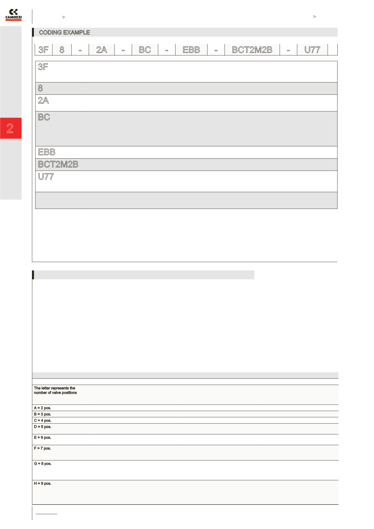
CODING EXAMPLE
3F
CONNECTION:
3F = Profibus-DP
3R = DeviceNet
3G = CANopen
8
SOLENOID VALVES PORTS:
8 = 1/8
2A
ELECTRIC INPUTS MODULES:
0 = no module
A = module 8 input M8
BC
ELECTRIC OUTPUTS MODULES:
0 = no module
B = 4 outputs M12 duo
C = 8 outputs SUB-D 37 pin
D = 16 outputs SUB-D 37 pin
E = 24 outputs SUB-D 37 pin
F = 32 outputs SUB-D 37 pin
EBB
SUB-BASES COMPOSITION:
see below
BCT2M2B
VALVES FUNCTIONS:
see the following page
U77
SOLENOID TYPE:
MATERIAL DIMENSION VOLTAGE
G = PA 7 = 22 x 22 7 = 24V DC
U = PET
VERSIONS:
= standard
S = special (to be specified)
3F8-2A-BC-EBB-BCT2M2B-U77 = Valve Island with Fieldbus node Profibus-DP, 2x inlet modules, 1x outlet B mod. + 1x outlet C mod., subbase of 6 pos., valve composed by 3x
mod. of 2 pos., 1x solenoid valve (SV) mod. B, 1x SV mod. C, separation channels 1/3/5, 2x SV mod. M, 2x SV mod. B, solenoids mod. U77.
3F 8 -
2A - BC - EBB - BCT2M2B - U77
The valve island code is always read from left to right, the electrical module is positioned to the side of the pneumatic manifold, as
on the photo on page 2.3.07.01. It is also possible to create 2 or more pressure/exhaust zones in the valve island by inserting the
diaphragm Mod. CNVL-TP between the modules.
The letter represents the
number of valve positions
Number of valve positions,
showing the combination
of the modules from which
the valve island is built.
Configuration code
n° of positions
Configuration code
of the sub-base
A = 2 pos.
(2)
A
A - B
B = 3 pos.
(3)
B
A - B
C = 4 pos.
(2) (2)
C
A - B
D = 5 pos.
(3) (2)
(2) (3)
D
D
A - B
A - D
E = 6 pos.
(3) (3)
(2) (2) (2)
E
E
A - B
B - B
F = 7 pos.
(2) (3) (2)
(2) (2) (3)
(3) (2) (2)
F
F
F
A - B
B - B
B - D
G = 8 pos.
(3) (3) (2)
(2) (3) (3)
(2) (2) (2) (2)
(3) (2) (3)
G
G
G
G
A - B
A - D
B - B
B - D
H = 9 pos.
(3) (3) (3)
(3) (2) (2) (2)
(2) (3) (2)(2)
(2) (2) (3) (2)
(2) (2) (2) (3)
H
H
H
H
H
A - B
B - B
B - D
B - F
B - H
CONFIGURATION TABLE OF THE VALVE ISLAND