


 608 / 1144

Products designed for industrial applications.
General terms and conditions for sale are available on
www.camozzi.com.2
Series H valve islands
CONTROL >
CATALOGUE
>
Release 8.7
/3.15.23
2
CONTROL
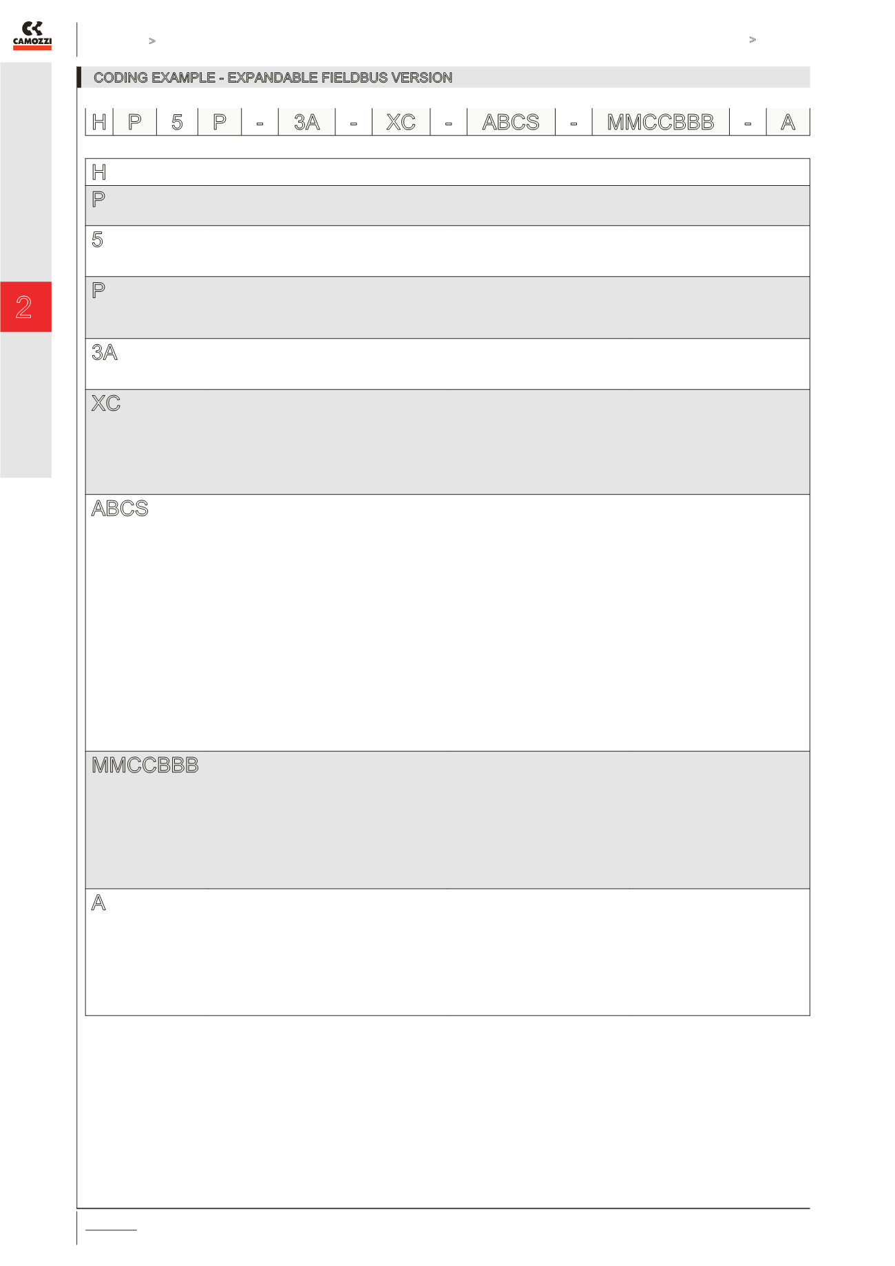
H
SERIES
P
TYPE:
P = Pneumatic
A = Accessories
5
SIZE:
1 = 10.5
2 = 21
5 = Mixed
P
ELECTRICAL CONNECTION:
P = Profibus-DP
C = CANopen
D = DeviceNet
E = Expansion for P-C-D only
3A
INPUT MODULES:
0 = Without inputs
A = 8 Input M8 *
* not for DeviceNet version
XC
OUTPUT MODULES:
0 = no module
B = 4 OutputlM12 DUO
C = 8 Output Sub-D 37 pin
D = 16 Output Sub-D 37 pin
E = 24 Output Sub-D 37 pin
F = 32 Output Sub-D 37 pin
X = Pneum. Electr. Interface for outlets
Y = Pneum. Electr. Interface + external power supply
ABCS
SUB-BASES FOR SOLENOID VALVES
Sub-bases for 2 solenoid valves size 1 (*):
A (AZ) = M7 threads
B (BZ) = 4 fittings for tube Ø4
C (CZ) = 4 fittings for tube Ø6
D (DZ) = channel 1, 3, 5 closed - M7 threads
E (EZ) = channel 1, 3, 5 closed - cartridges tube Ø4
F (FZ) = channel 1, 3, 5 closed - cartridges tube Ø6
G (GZ) = channel 3, 5 closed - M7 threads
H (HZ) = channel 3, 5 closed - cartridges tube Ø4
I (IZ) = channel 3, 5 closed - cartridges tube Ø6
L (LZ) = channel 1 closed - M7 threads
M (MZ) = channel 1 closed - cartridges tube Ø4
N (NZ) = channel 1 closed - cartridges tube Ø6
(*) Sub-bases with “Z” at the end of their code
are used with monostable solenoid valves
Sub-bases for solenoid valves size 2:
Q = G 1/8 threads
R = cartdriges tube Ø6
S = cartdriges tube Ø8
SUB-BASES FOR SUPPLY
Sub-bases for pneumatic supply:
X = supplementary supply and exhaust
Y = supplementary supply and exhaust
with integrated silencer
W = supply from the exhausts
Sub-bases for electrical supply:
K = separation of electrical supply
SEALS
T = diaphragm seal - channel 1;3;5
U = diaphragm seal - channel 1
V = diaphragm seal - channel 3; 5
MMCCBBB
SOLENOID VALVES
Size 1 and Size 2:
M = 5/2 Monostable
B = 5/2 Bistable
V = 5/3 Centres Closed
C = 2 x 3/2 NC
A = 2 x 3/2 NO
G = 1 x 3/2 NC + 1 x 3/2 NO
E = 2 x 2/2 NC
F = 2 x 2/2 NO
I = 1 x 2/2 NC + 1 x 2/2 NO
L = free position
Solenoid valve + Pressure regulator
on channel 1 - Size 2 ONLY:
N = 5/2 Monostable
P = 5/2 Bistable
Q = 5/3 Centres Closed
R = 2 x 3/2 NC
S = 2 x 3/2 NO
T = 1 x 3/2 NC + 1 x 3/2 NO
U = 2 x 2/2 NC
X = 2 x 2/2 NO
Y = 1 x 2/2 NC + 1 x 2/2 NO
A
TERMINAL PLATES
Threaded:
A = 1; 12/14 in common
3/5; 82/84 threaded ports
B = 1; 12/14 separated
3/5; 82/84 threaded ports
C = 1; 12/14 in common
3/5; 82/84 with integrated silencer
D = 1; 12/14 separated
3/5; 82/84 with integrated silencer
TERMINAL PLATES
With cartridges Ø 8 :
E = 1; 12/14 in common
3/5; 82/84 conveyable
F = 1; 12/14 separated
3/5; 82/84 conveyable
G = 1; 12/14 in common
3/5; 82/84 with integrated silencer
H = 1; 12/14 separated
3/5; 82/84 with integrated silencer
TERMINAL PLATES
With cartridges Ø 10 :
I = 1; 12/14 in common
3/5; 82/84 conveyable
L = 1; 12/14 separated
3/5; 82/84 conveyable
M = 1; 12/14 in common
3/5; 82/84 with integrated silencer
N = 1; 12/14 separated
3/5; 82/84 with integrated silencer
X, Y and K sub-bases will be equipped with threads or cartridges of the same size of port 1, see the choice “Type of terminal plates”. In presence of identical consequent codes
both for sub-bases and for valves, you need to substitute the letter with the number. Ex: HP5P-AAA-XC-ABCS-MMCCBBB-A is converted to Ex: HP5P-3A-XC-2M2C3B-A.
CODING EXAMPLE - EXPANDABLE FIELDBUS VERSION
H P 5 P - 3A - XC - ABCS - MMCCBBB - A