


 611 / 1144

Products designed for industrial applications.
General terms and conditions for sale are available on
www.camozzi.com.Series H valve islands
CATALOGUE
2
/3.15.26
2
>
Release 8.7
CONTROL >
CONTROL
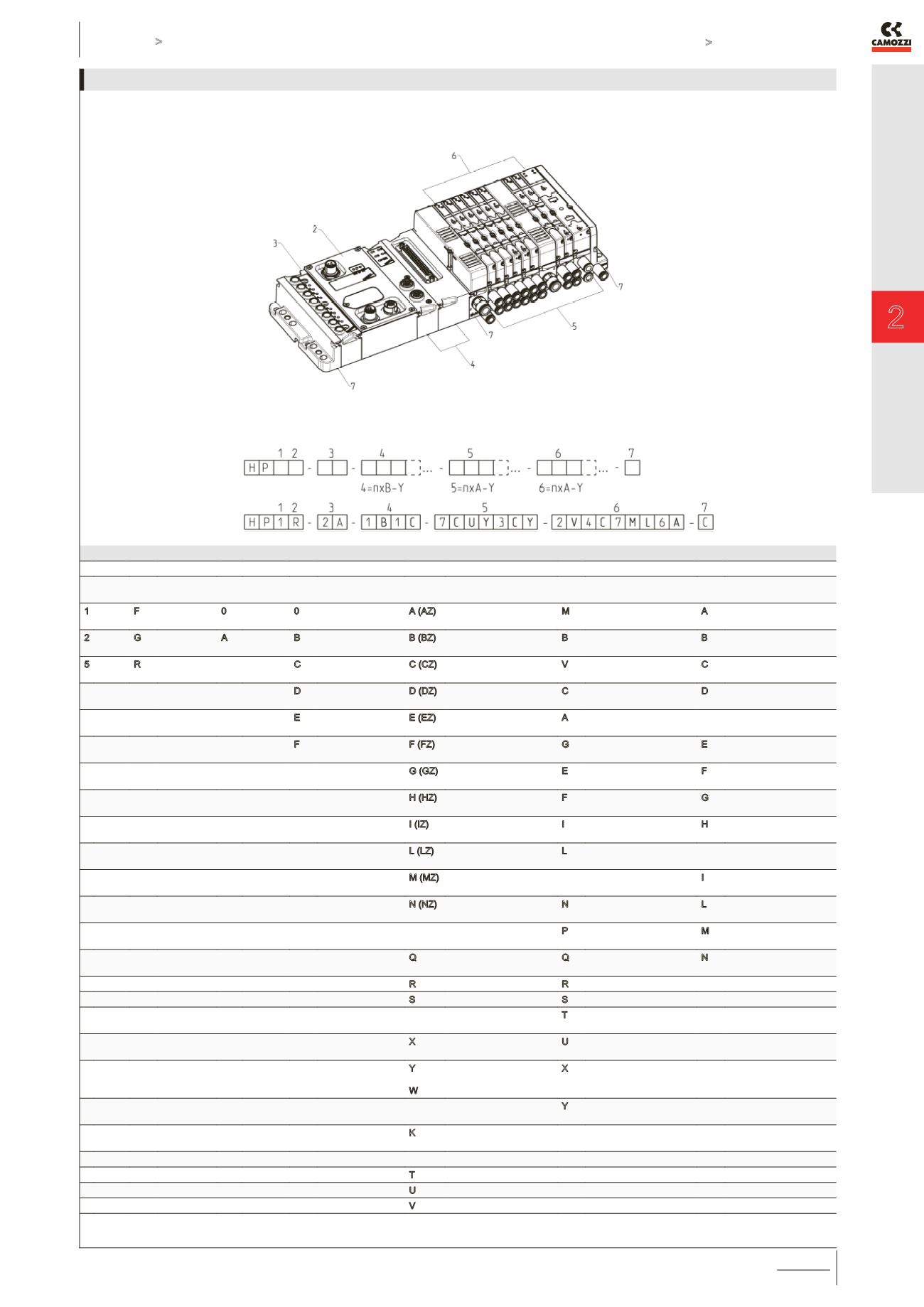
CODING - INDIVIDUAL FIELDBUS VERSION [ Unused input modules with electrical connections type R ]
CODE
HP ( 1 )
( 2 )
( 3 )
( 4 )
( 5 )
( 6 )
( 7 )
Size
Electrical
Connection
Input
Modules
Output Modules
Type of sub-bases and
seals
Type of solenoid valve
Size 1 and 2
Type of threaded terminal
plates
1 10,5 F Profibus-DP 0 no module 0
no module
A (AZ)
M7 threads
M
5/2 Monostable
A
1; 12/14 in common
3/5; 82/84 threaded
2 21 G CANopen A 8 Input M8 B 4 outputs M12 duo B (BZ)
fittings tube Ø4
B
5/3 Bistable
B
1; 12/14 separate;
3/5; 82/84 threaded
5 Mixed R DeviceNet
C 8 outputs SUB-D
37 pin
C (CZ)
fittings tube Ø6
V
5/3 Centres Closed C 1; 12/14 in common;
3/5; 82/84 w. silencer
D 16 outputs SUB-D
37 pin
D (DZ)
channel 1; 3; 5 closed
M7 threads
C
2 x 3/2 NC
D
1; 12/14 separate;
3/5; 82/84 w. silencer
E 24 outputs SUB-D
37 pin
E (EZ)
channel 1; 3; 5 closed
cartridge Ø4
A
2 x 3/2 NO
FITTINGS TUBE Ø8
ON PORT 1
F 32 outputs SUB-D
37 pin
F (FZ)
channel 1; 3; 5 closed
cartridge Ø6
G
1 x 3/2 NC +
1 x 3/2 NO
E
1; 12/14 in common
3/5; 82/84 conveyable
G (GZ)
channel 3; 5 closed
M7 threads
E
2 x 2/2 NC
F
1; 12/14 separate
3/5; 82/84 conveyable
H (HZ)
channel 3; 5 closed
cartridge Ø4
F
2 x 2/2 NO
G 1; 12/14 in common
3/5; 82/84 w. silencer
I (IZ)
channel 3; 5 closed
cartridge Ø6
I
1 x 2/2 NC +
1 x 2/2 NO
H
1; 12/14 separate
3/5; 82/84 w. silencer
L (LZ)
channel 1 closed
threaded M7
L
Free position
FITTINGS TUBE Ø10
ON PORT 1
M (MZ)
channel 1 closed
cartridge Ø4
SOL. VALVE+PR. REG.
LINE 1, SIZE 2 ONLY
I
1; 12/14 in common
3/5; 82/84 conveyable
N (NZ)
channel 1 closed
cartridge Ø6
N
5/2 Monostable
L
1; 12/14 separate
3/5; 82/84 conveyable
SUB-BASE FOR
VALVES SIZE 2
P
5/3 Bistable
M 1; 12/14 in common 3/5;
82/84 w. silencer
Q
G1/8 thread
Q 5/3 Centres Closed N
1; 12/14 separate
3/5; 82/84 w. silencer
R
fittings tube Ø6
R
2 x 3/2 NC
S
fittings tube Ø8
S
2 x 3/2 NO
SUPPLEM. SUPPLY
AND EXHAUST
T
1 x 3/2 NC +
1 x 3/2 NO
X
Supplem. supply
and exhaust
U
2 x 2/2 NC
Y
W
Supplem. supply and
exhaust with silencer
Supply from exhausts
X
2 x 2/2 NO
ELECT. SEP. + SUPPL.
PNEUM. SUPPLY
Y 1 x 2/2 NC + 1 x 2/2 NO
K
Electr. supply sep. and
supplem. pneum. supply
SEALS
T
Diaphr. channel 1; 3; 5
U
Diaphr. channel 1
V
Diaphr. channel 3; 5