


 765 / 1144

Products designed for industrial applications.
General terms and conditions for sale are available on
www.camozzi.com.Series LRWA analogic proportional servo valves
CATALOGUE
2
/15.11.03
2
>
Release 8.7
CONTROL >
CONTROL
LRWA0 SERVO VALVES - PNEUMATIC INSTALLATION
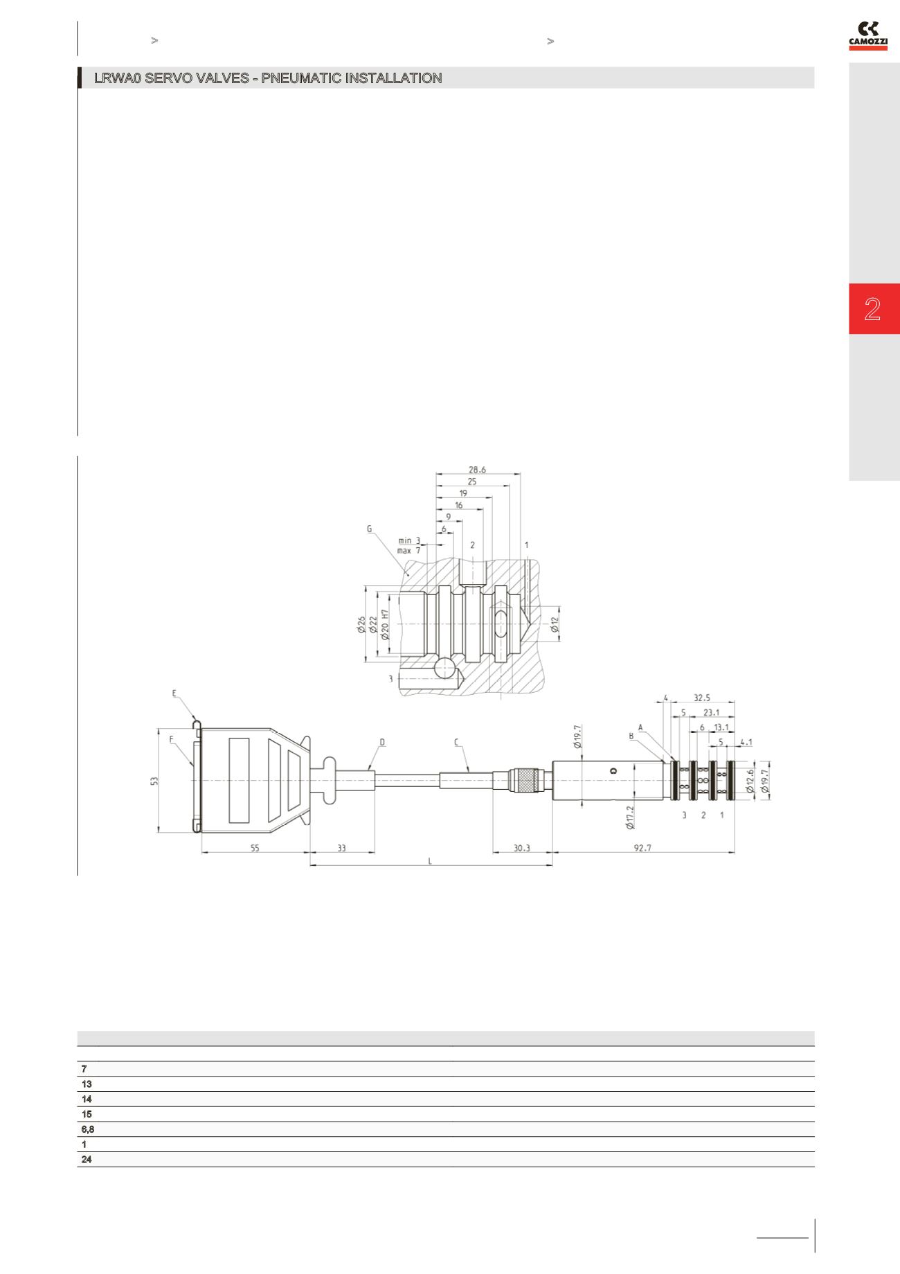
The servo valve works as follows: if the command signal or setpoint is lower than 50%, the valve establishes a link between
connection 1 and connection 2; then the air passes between the inlet and the outlet. If the setpoint value is higher than 50%, the port
2 is connected with the exhaust 3. For a better understanding, please see the flow diagram on page 2.15.11.2.
THE LENGTH OF THE LEADS SHOULD BE AS SHORT AS POSSIBLE, BETWEEN VALVE-OUTLET AND LOAD NORMALLY
NOT MORE THAN 2 mts.
Drawing legend:
1 = Supply
2 = Port
3 = Exhaust
A = O-ring 17x1,5
B = fixation slot
C = bending radius >50
D = bending radius >25
F = sub-d-25 pins (male)
G = cartridge fitting block
L = cable length
ELECTRICAL CONNECTIONS
PIN
FUNCTION
NOTES
7
power supply +24 VDC
13
GND power supply
14
GND Input command signal
15
Input command signal
6,8
Internal reference potential
never connect to other GNDs!
1
Testpoint motor voltage
+/- 10 V vs. pin 6
24
Testpoint slide position
+/- 1 V vs. pin 6