


 767 / 1144

Products designed for industrial applications.
General terms and conditions for sale are available on
www.camozzi.com.Series LRWA analogic proportional servo valves
CATALOGUE
2
/15.11.05
2
>
Release 8.7
CONTROL >
CONTROL
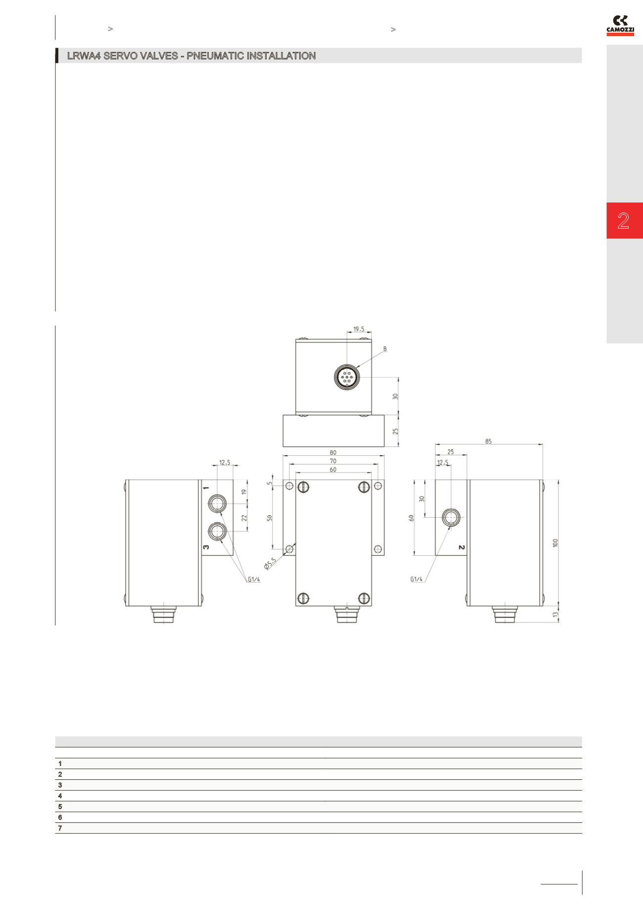
LRWA4 SERVO VALVES - PNEUMATIC INSTALLATION
The servo valve works as follows: if the command signal or setpoint is lower than 50% the valve establishes a link between
connection 1 and connection 2; then the air passes between the inlet and the outlet. If the setpoint value is higher than 50%, the port
2 is connected with the exhaust 3. For a better understanding, please see the flow diagram on page 2.15.11.2.
THE LENGTH OF THE LEADS SHOULD BE AS SHORT AS POSSIBLE, BETWEEN VALVE-OUTLET AND LOAD NORMALLY
NOT MORE THAN 2 mts.
ELECTRICAL CONNECTIONS (male connector M16 7 poles)
PIN
FUNCTION
NOTES
1
power supply +24 VDC
2
GND power supply
3
Input command signal (Setpoint)
4
GND Input command signal
Pin 4 and 2 should be connected.
5
NC
6
NC
7
NC