


 771 / 1144

Products designed for industrial applications.
General terms and conditions for sale are available on
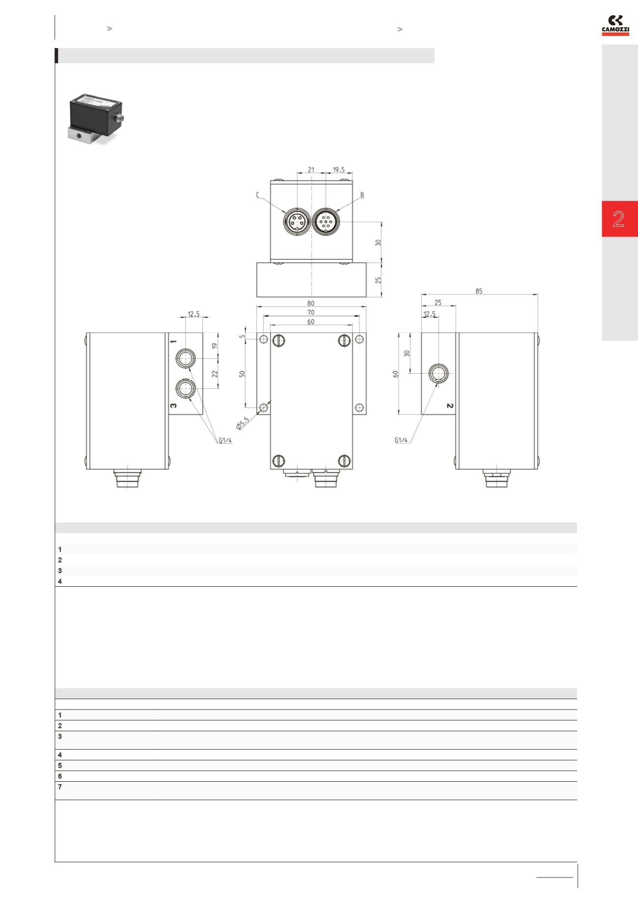
www.camozzi.com.Series LRPA4 servo valves - Pressure control
CATALOGUE
2
/15.25.03
2
>
Release 8.7
CONTROL >
CONTROL
Accessories are available in the section 2.15.35
B - Supply connector (7 poles male)
PIN
FUNCTION
NOTES
1
Power supply +24 VDC
2
Power supply GND
3
Input command signal
(Setpoint Value)
0-10 VDC or 0-20 mA or 4-20mA. The output pressure always follows this signal that has to has to be as stable as possible. For example: if the
sensor has a range of 10 bar and the Setpoint has a Ripple error of 10 mV, this will generate a ripple of 10 mbar on the output.
4 GND input command signal
Pin 4 and 2 must be connected.
5
Output “ERROR”
see technical data
6
Output “LIMIT”
see technical data
7 Output signal of the internal
sensor
0-10 VDC. The accuracy-fault of that signal is 2% F.S. and there is an offset of approx. 150 mV.
B = male connector M16 7 poles for supply
C = female connector M16 4 poles for external transducer
Female connector M16 4 poles for external transducer
PIN
FUNCTION
NOTES
1
Electrical supply to the external transducer
24 V DC
2
GND
Internal connection to GND power supply
3
Input from the external transducer
0-10 V o 0-20 mA o 4-20 mA
4
NC
LRPA4-xx-x-2/3/5-00 SERVO VALVES - PNEUMATICAL INSTALLATION