
Products designed for industrial applications.
General terms and conditions for sale are available on
www.camozzi.com.Series 52 cylinders
CATALOGUE
1
/8.10.03
1
>
Release 8.8
MOVEMENT >
MOVEMENT
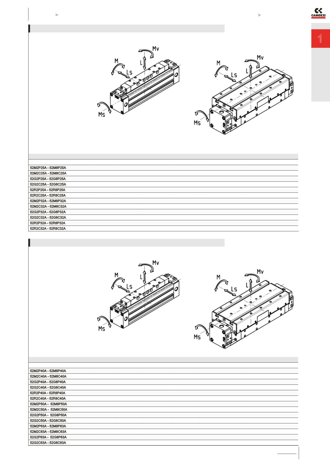
COMPLEX LOADS
If more than one force and torque is
applied simultaneously, they have
to be calculated according to the
following formula: L/L (max)+ Ls/Ls
(max)+ M/M (max)+ Ms/Ms (max)+
Mv/Mv (max ) ≤1.
For models 52M, the load and torque
values refer to the center of the tube.
For models 52G/52R the load and
torque values refer to the center
point of the external guide. It is
also necessary for these models to
guarantee on the fixing surface a max
0.1 flatness’s value.
The load and torque values
refer to a velocity of: Models
52M/52G/52M/52G ≤ 0,2 m/s, models
52R ≤ 2 m/s.
For the adjustment coefficients of
loads see page 1.8.10.04
Table showing the maximum permitted loads and torque forces
Mod.
L Max ( N )
Ls Max ( N )
M Max ( Nm )
Ms Max ( Nm )
Mv Max ( Nm )
Mass at 0 mm stroke (kg)
Additional mass per 100 mm (kg)
52M2P25A - 52M8P25A 270
-
13
2,5
11
0,88
0,30
52M2C25A - 52M8C25A 270
-
8
2
7
0,62
0,30
52G2P25A - 52G8P25A 580
580
23
10
23
1,31
0,30
52G2C25A - 52G8C25A 340
340
9
5
9
0,88
0,30
52R2P25A - 52R8P25A
850
1300
65
35
105
1,97
0,42
52R2C25A - 52R8C25A 850
1300
29
35
64
1,33
0,42
52M2P32A - 52M8P32A 300
-
30
3
24
1,40
0,39
52M2C32A - 52M8C32A 300
-
15
3
12
0,96
0,39
52G2P32A - 52G8P32A 850
850
33
15
33
2,09
0,39
52G2C32A - 52G8C32A 460
460
14
6,5
14
1,35
0,39
52R2P32A - 52R8P32A
900
1500
79
40
125
2,96
0,48
52R2C32A - 52R8C32A 900
1500
36
40
76
1,91
0,48
LOADS AND TORQUE FORCES Ø 25 - 32
COMPLEX LOADS
If more than one force and torque is
applied simultaneously, they have
to be calculated according to the
following formula: L/L (max)+ Ls/Ls
(max)+ M/M (max)+ Ms/Ms (max)+
Mv/Mv (max ) ≤1.
For models 52M, the load and torque
values refer to the center of the tube.
For models 52G/52R the load and
torque values refer to the center point
of the guide.
The load and torque values refer
to a velocity of: Models 52M/52G
≤0,2 m/s
Models 52R ≤2 m/s
If the velocity exceeds 0.2m/s for
the models 52M/52G, the load and
torque values have to be multiplied
by the coefficients according to the
table.
For the adjustment coefficients of
loads see page 1.8.10.04
Table showing the maximum permitted loads and torque forces
Mod.
L Max ( N )
Ls Max ( N )
M Max ( Nm )
Ms Max ( Nm )
Mv Max ( Nm )
Mass at 0 mm stroke (kg)
Additional mass per 100 mm (kg)
52M2P40A - 52M8P40A
650
-
60
4
54
2,41
0,52
52M2C40A - 52M8C40A 650
-
30
4
27
1,65
0,52
52G2P40A - 52G8P40A 1120
1120
60
25
60
3,58
0,52
52G2C40A - 52G8C40A
600
600
25
11
25
2,30
0,52
52R2P40A - 52R8P40A
1200
2000
190
67
118
5,89
0,74
52R2C40A - 52R8C40A 1200
2000
85
67
72
3,84
0,74
52M2P50A - 52M8P50A 800
-
80
17
74
5,30
0,96
52M2C50A - 52M8C50A 800
-
38
17
32
3,50
0,96
52G2P50A - 52G8P50A 1550
1500
200
70
200
7,28
0,96
52G2C50A - 52G8C50A
820
800
60
40
60
4,63
0,96
52M2P63A - 52M8P63A 1400
-
110
17
100
8,10
1,32
52M2C63A - 52M8C63A 1400
-
50
17
48
5,40
1,32
52G2P63A - 52G8P63A 2200
2000
300
102
300
11,02
1,32
52G2C63A - 52G8C63A 1100
1100
105
56
105
7,10
1,32
LOADS AND TORQUE FORCES Ø 40 - 50 - 63


