
Products designed for industrial applications.
General terms and conditions for sale are available on
www.camozzi.com.Solenoids
CATALOGUE
2
/2.35.03
2
>
Release 8.8
CONTROL >
CONTROL
Solenoids Mod. G9... can be replaced on all other Series
A solenoid valves or pilots allowing to change the valve
functioning from:
- unstable functioning system (spring return)
to:
- stable functioning system (memory)
The stable functioning has the following advantages:
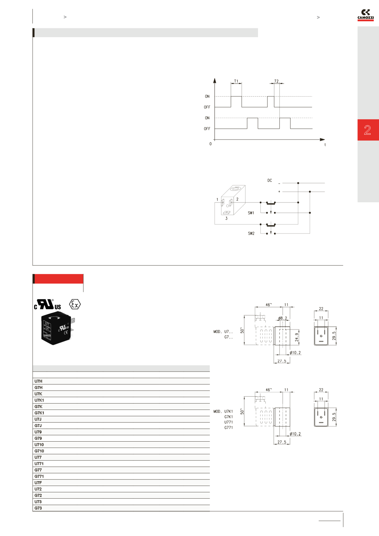
- with an impulse of about 20 ms after which the valve always
remains in the controlled position.
- the valve remains in the controlled position (opened or
closed) even if there is no power.
- when normally opened valves should be used, it is not
necessary to use valves with special mechanical parts as a NC
valve becomes a NO valve just by changing the control
impulse sequence.
- The impulse control system facilitates the utilization with
electronic circuits. The minimum required impulse for the
function is 20 ms; if, for circuit reasons, the impulse last for a
longer period, there is no danger of heating.
- magnet attraction command = Actuation SW1
- magnet release command = Actuation SW2
If the solenoids are mounted in batteries, a magnetic scheme
type G90/L should be used.
To facilitate the cabling a special connector is available, which
contains a circuit which realises the inversion of the power
supply to the solenoid, indispensable for the PLC command,
122-892 P with common positive or 122-893 N with common
negative.
Description of solenoids Mod. G9...
Solenoids Mod. U7... / U7*EX and Mod. G7...
Mod.
Sol. volt. (1)
Pow. abs. (1)
Sol. volt. (2)
Pow. abs. (2) Sol. volt. (3) Pow. abs. (3)
U7H 12 V DC
3.1 W 24V - 50/60 Hz
3.5 VA
G7H 12 V DC
3.1 W 24V - 50/60Hz
3.5 VA
U7K 110V - 50/60Hz 3.8 VA 125V - 50/60Hz 5.5 VA 72 V DC 4.8 W
U7K1 110V - 50/60Hz 5.8 VA 125V - 50/60Hz 8.3 VA 72 V DC 5.6 W
G7K 110V - 50/60Hz 3.8 VA 125V - 50/60Hz 5.5 VA 72 V DC 4.8 W
G7K1 110V - 50/60Hz 5.8 VA 125V - 50/60Hz 8.3 VA 72 V DC 5.6 W
U7J 230V - 50/60Hz 3.5 VA 240V - 50/60Hz
4 VA
G7J 230V - 50/60Hz 3.5 VA 240V - 50/60Hz
4 VA
U79
48 V DC
3.1 W
G79
48 V DC
3.1 W
U710 110 V DC
3.2 W
G710 110 V DC
3.2 W
U77
24 V DC
3.1 W 48V - 50/60Hz
3.8 VA
U771
24 V DC
3.1 W 48V - 50/60Hz
3.8 VA
G77
24 V DC
3.1 W 48V - 50/60Hz
3.8 VA
G771
24 V DC
3.1 W 48V - 50/60Hz
3.8 VA
U7F 380V - 50/60Hz
7 VA
U72
12 V DC
5 W
G72
12 V DC
5 W
U73
24 V DC
5 W
G73
24 V DC
5 W
Electrical connection: bipolar plus earth
Norm: DIN EN 175 301-803-B
Solenoid material: U7* = PET: G7* = PA
To order the ATEX version of Mod. U7 (not available
for Mod. U7F, U7K1 with voltage 125V 50/60Hz) it is
necessary to add EX at the end of the code.
Mod. U7*EX marked:
II 3G Ex nA IIC T4 Gc X IP65
II 3D Ex tc IIIC 130°C Dc X
Notes to the table:
Sol. volt. = Solenoid voltage
Pow. abs. = Power absorption
Mod. U7K1, G7K1, U771 and
G771 are to be used only with
sol. valves series A, NO in line.


