
Products designed for industrial applications.
General terms and conditions for sale are available on
www.camozzi.com.Series HN valve islands
CATALOGUE
2
/3.40.03
2
>
Release 8.8
CONTROL >
CONTROL
HN
SERIES
5
SIZE:
1 = 10.5
2 = 21
5 = Mixed
M
ELECTRICAL CONNECTION:
M = Multipole 25 pin PNP
N = Multipole 25 pin NPN
H = Multipole 37 pin PNP
L = Multipole 37 pin NPN
03A
CONNECTION:
000 = without connector/cable
CONNECTOR WITH CABLE AXIAL OUTPUT:
03A = 3m
05A = 5m
10A = 10m
15A = 15m
20A = 20m
25A = 25m
CONNECTOR WITH CABLE RADIAL OUTPUT:
03R = 3m
05R = 5m
10R = 10m
15R = 15m
20R = 20m
25R = 25m
CONNECTOR WITHOUT CABLE:
4XA = 25 pins axial
4XR = 25 pins radial
9XA = 37 pins axial
9XR = 37 pins radial
2Q4AZ2A
SUBBASES
FOR 2 SOLENOID VALVES SIZE 1 (*):
A (AZ) = M7 threads
B (BZ) = 4 fittings for tube Ø4
C (CZ) = 4 fittings for tube Ø6
D (DZ) = channel 1, 3, 5 closed; M7 threads
E (EZ) = channel 1, 3, 5 closed; cartridges tube Ø4
F (FZ) = channel 1, 3, 5 closed; cartridges tube Ø6
G (GZ) = channel 3, 5 closed; M7 threads
H (HZ) = channel 3, 5 closed; cartridges tube Ø4
I (IZ) = channel 3, 5 closed; cartridges tube Ø6
L (LZ) = channel 1 closed; M7 threads
M (MZ) = channel 1 closed; cartridges tube Ø4
N (NZ) = channel 1 closed; cartridges tube Ø6
(*) Subbases with “Z” at the end of their code
are used with monostable solenoid valves
FOR SOLENOID VALVES SIZE 2:
Q = G 1/8 threads
R = cartridges for tube Ø6
S = cartridges for tube Ø8
SUBBASES
FOR PNEUMATIC SUPPLY:
X = supplementary supply and exhaust
Y = supplementary supply and exhaust
with integrated silencer
W = supply from the exhausts
FOR ELECTRICAL SUPPLY:
K = separation of electrical supply
SEALS:
T = diaphragm on channels 1, 3, 5
U = diaphragm on channel 1
V = diaphragm on channels 3, 5
2B8M4C
SOLENOID VALVES
Size 1 and 2:
0 = island without solenoid valves
M = 5/2 Monostable
B = 5/2 Bistable
V = 5/3 Centres Closed
C = 2 x 3/2 NC
A = 2 x 3/2 NO
G = 1 x 3/2 NC + 1 x 3/2 NO
E = 2 x 2/2 NC
F = 2 x 2/2 NO
I = 1 x 2/2 NC + 1 x 2/2 NO
L = free position
SOLENOID VALVE + PRESSURE REGULATOR
on channel 1 (size 2 only):
N = 5/2 Monostable
P = 5/2 Bistable
Q = 5/3 Centres Closed
R = 2 x 3/2 NC
S = 2 x 3/2 NO
T = 1 x 3/2 NC + 1 x 3/2 NO
U = 2 x 2/2 NC
X = 2 x 2/2 NO
Y = 1 x 2/2 NC + 1 x 2/2 NO
A
THREADED TERMINAL PLATES:
A = 1, 12/14 in common
3/5, 82/84 threaded ports
B = 1, 12/14 separated
3/5, 82/84 threaded ports
C = 1, 12/14 in common
3/5, 82/84 with integrated silencer
D = 1, 12/14 separated
3/5, 82/84 with integrated silencer
TERMINAL PLATES with
FITTINGS FOR TUBE Ø 8 on PORT 1:
E = 1, 12/14 in common
3/5, 82/84 conveyable
F = 1, 12/14 separated
3/5, 82/84 conveyable
G = 1, 12/14 in common
3/5, 82/84 with integrated silencer
H = 1, 12/14 separated
3/5, 82/84 with integrated silencer
TERMINAL PLATES with
FITTINGS FOR TUBE Ø 10 on PORT 1:
I = 1, 12/14 in common
3/5, 82/84 conveyable
L = 1, 12/14 separated
3/5, 82/84 conveyable
M = 1, 12/14 in common
3/5, 82/84 with integrated silencer
N = 1, 12/14 separated
3/5, 82/84 with integrated silencer
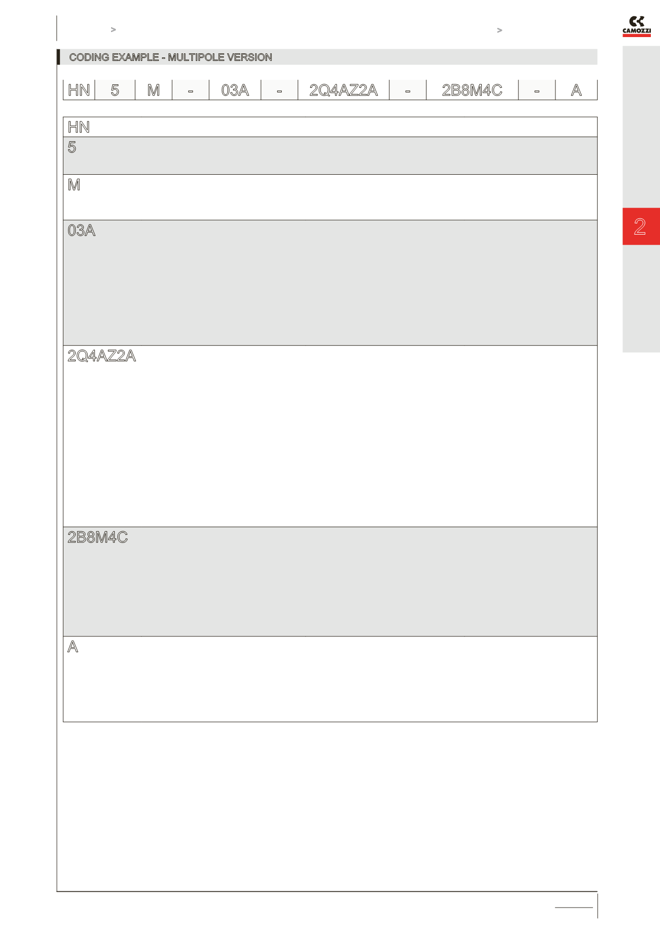
In presence of identical consequent codes both for the subbases as for the valves you need to substitute the letter with the number.
Ex: HN5M-03A-ABCS-MMCCBBB-A is converted to HN5M-03A-ABCS-2M2C3B-A.
CODING EXAMPLE - MULTIPOLE VERSION
HN 5 M -
03A -
2Q4AZ2A -
2B8M4C -
A


