
Products designed for industrial applications.
General terms and conditions for sale are available on
www.camozzi.com.Series LR digital proportional servo valves
CATALOGUE
2
/15.32.06
2
>
Release 8.8
CONTROL >
CONTROL
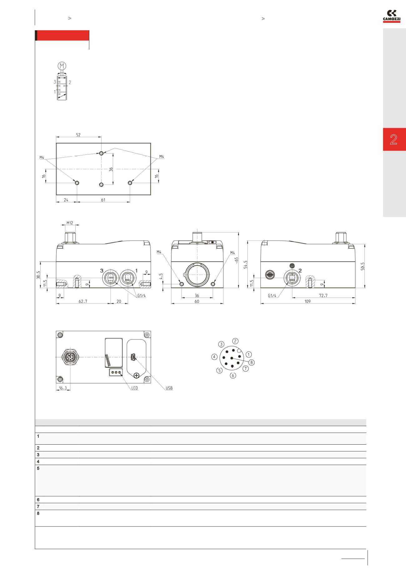
Series LR digital proportional servo valves - dimensions
The detailed user and maintenance manual and
the Hardware configuration Software of the valve is
available online at
http://catalogue.camozzi.com.
PIN SIGNAL
DESCRIPTION
1
+5V
+5V power supply for external potentiometer transducer (ref. GND).
If used, it is necessary to connect RIF- with GND.
2
24 V DC
24V DC power supply (logic and motor): connect to the positive pole of the 24V DC power supply (ref. GND)
3
RIF-
GND reference or NEGATIVE pole of the command signal (0-10V / 4-20mA / ±10V)
4
RIF+
POSITIVE reference of the command signal (0-10V / 4-20mA / ±10V)
5
EXT
for LRWD valve:
for LRXD valve:
for LRPD valve:
not used
feedback signal of the external transducer 0-5V / 0-10V / 4-20mA (ref. RIF-)
feedback signal of the external transducer 0-5V / 0-10V / 4-20mA (ref. RIF-).
To be used only with LRPD2 valve versions with external sensor.
6
FBK
feedback signal 0-10V / 4-20mA (ref. GND)
7
GND
common (reference pin 1 and 2): connect to the negative pole of the 24V DC power supply (compulsory)
8
ERR
for LRWD and LRPD valve:
for LRXD valve:
error signal (output) 0-24V (ref. GND)
command signal 0-10V for slave valve (ref. GND)


