


 35 / 84

Products designed for industrial applications.
General terms and conditions for sale are available on
www.camozzi.com.Series 5E electromechanical axis
C_Electrics
1
33
>
2017
MOVEMENT >
MOVEMENT
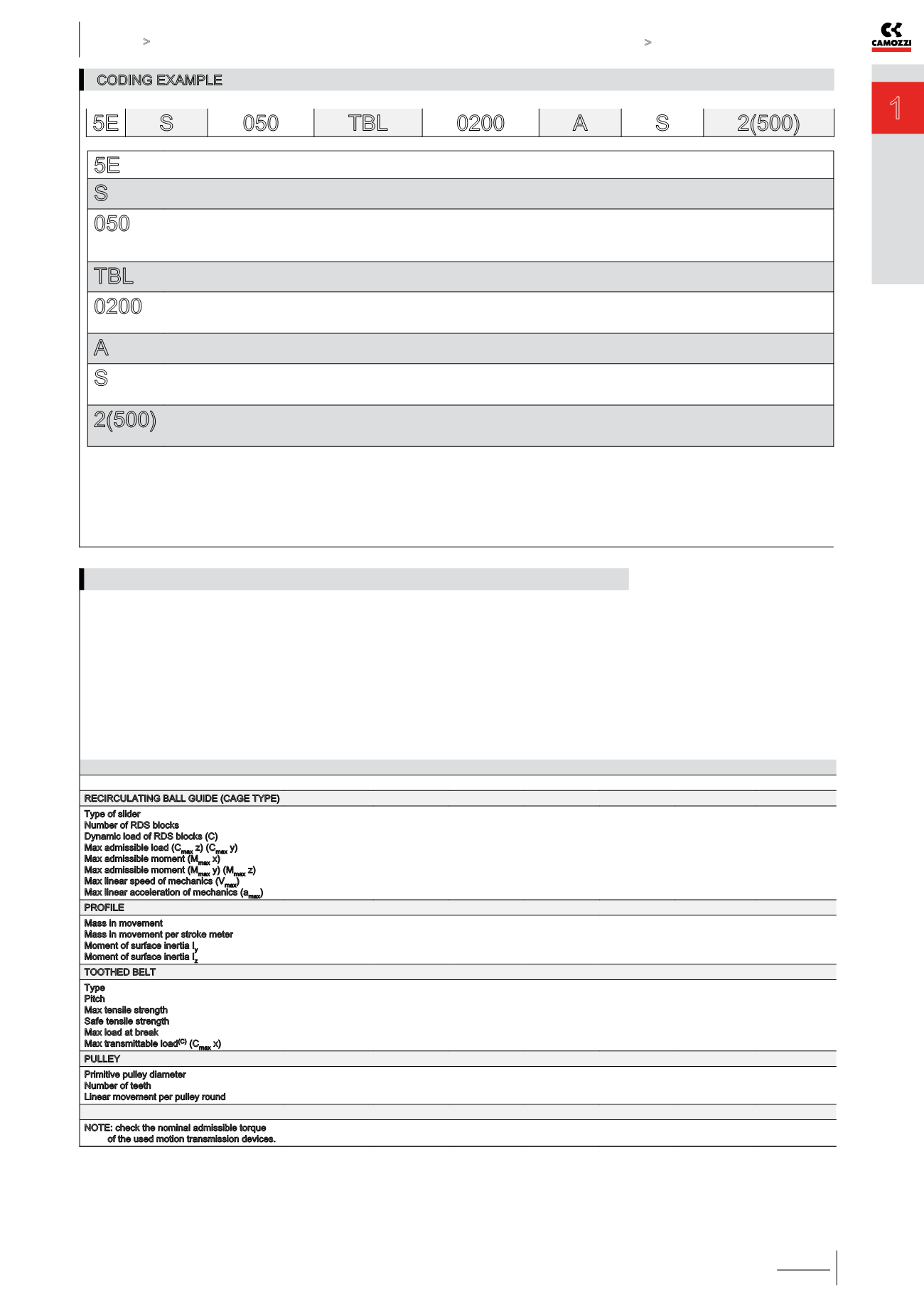
CODING EXAMPLE
5E
SERIES
S
PROFILE:
S = square section
050
FRAME SIZE:
050 = 50x50 mm
065 = 65x65 mm
080 = 80x80 mm
TBL
TRANSMISSION:
TBL = toothed belt
0200
STROKE [C]:
0050 ÷ 4000 mm for size 050
0050 ÷ 6000 mm for sizes 065 and 080
A
VERSION:
A = standard
S
TYPE OF SLIDER:
S = standard
L = long
2(500)
NUMBER OF SLIDERS:
1 = 1 slider
2(____) = 2 sliders at (____) mm step [ only for sliders type “S” ]
5E S 050
TBL
0200
A S 2(500)
(A)
Value refers to a covered distance of 2000 Km with fully supported system.
(B)
The “suggested” speed is not the mechanical limit of the unit but represents the best compromise between high load applied and high dynamics.
In case of particular requirements, please contact our technical assistance
(service@camozzi.com).
(C)
Value refers to 1500 rpm.
Measuring unit
Size 50
Size 50
Size 65
Size 65
Size 80
Size 80
RECIRCULATING BALL GUIDE (CAGE TYPE)
Type of slider
Number of RDS blocks
Dynamic load of RDS blocks (C)
Max admissible load (C
max
z) (C
max
y)
Max admissible moment (M
max
x)
Max admissible moment (M
max
y) (M
max
z)
Max linear speed of mechanics (V
max
)
Max linear acceleration of mechanics (a
max
)
pcs
N
N
Nm
Nm
m/s
m/s²
S
2
11640
3100
(A)
22.44
45.30
5
50
L
3
17460
5100
(A)
31.23
96.76
2.5
(B)
20
(B)
S
2
28400
8300
(A)
96.00
269.40
5
50
L
3
42600
12450
(A)
144.00
612.64
2.5
(B)
20
(B)
S
2
44600
13100
(A)
216.60
525.00
5
50
L
3
66900
19600
(A)
324.9
1193.17
2.5
(B)
20
(B)
PROFILE
Mass in movement
Mass in movement per stroke meter
Moment of surface inertia I
y
Moment of surface inertia I
z
kg
kg/m
mm
4
mm
4
0.45
0.13
1.89 ∙ 10
5
2.48 ∙ 10
5
0.62
0.13
1.89 ∙ 10
5
2.48 ∙ 10
5
1.10
0.21
4.94 ∙ 10
5
6.97 ∙ 10
5
1.51
0.21
4.94 ∙ 10
5
6.97 ∙ 10
5
2.30
0.41
1.23 ∙ 10
6
1.68 ∙ 10
6
3.11
0.41
1.23 ∙ 10
6
1.68 ∙ 10
6
TOOTHED BELT
Type
Pitch
Max tensile strength
Safe tensile strength
Max load at break
Max transmittable load
(C)
(C
max
x)
mm
N
N
N
N
20 AT 5 HP
5
1795
1110
7180
480
(C)
20 AT 5 HP
5
1795
1110
7180
480
(C)
32 AT 5 HP
5
2890
1786
11570
1150
(C)
32 AT 5 HP
5
2890
1786
11570
1150
(C)
32 AT 10 HP
10
6570
4061
26295
1400
(C)
32 AT 10 HP
10
6570
4061
26295
1400
(C)
PULLEY
Primitive pulley diameter
Number of teeth
Linear movement per pulley round
mm
z
mm/round
31.83
20
100
31.83
20
100
47.75
30
150
47.75
30
150
63.66
20
200
63.66
20
200
NOTE: check the nominal admissible torque
of the used motion transmission devices.
MECHANICAL CHARACTERISTICS