
Products designed for industrial applications.
General terms and conditions for sale are available on
www.camozzi.com.Series 5E electromechanical axis
C_Electrics
1
35
>
2017
MOVEMENT >
MOVEMENT
The correct dimensioning of the axis 5E, used individually or
in a cartesian system with several axes, you need to consider
some facts, both static and dynamic. Among these, the most
important are described on the following pages.
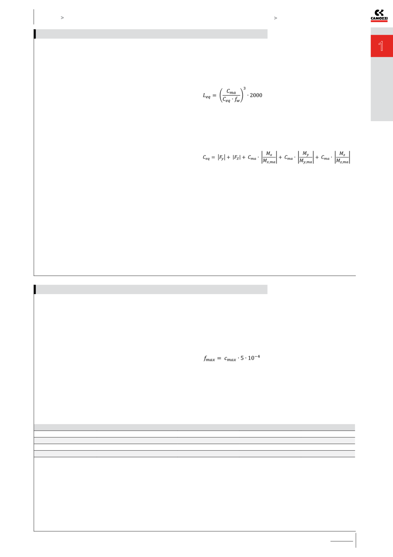
CALCULATION OF LIFE [km]
L
eq
= Life of the axis 5E [km]
C
ma
= Maximum admissible load [N]
C
eq
= Equivalent load [N]
f
w
= safety coefficient according to
the working conditions
CALCULATION OF EQUIVALENT LOAD
When compression/traction and side loads as well as bending
or torque moments act on the system, you need to calculate
the equivalent load acting on the system.
C
eq
= Equivalent load [N]
F
y
= Force acting along the Y-axis [N]
F
z
= Force acting along the Z-axis [N]
C
ma
= Max admissible load [N]
M
x
= Moment along X-axis [Nm]
M
y
= Moment along Y-axis [Nm]
M
z
= Moment along Z-axis [Nm]
M
(x,ma)
= Max admissible moment along X-axis [Nm]
M
(y,ma)
= Max admissible moment along Y-axis [Nm]
M
(z,ma)
= Max admissible moment along Z-axis [Nm]
How to calculate the life of the axis 5E
The electromechanical axis 5E is a self-supporting system and
can also be used between 2 or more supports without the need
of a continuous contact surface.
The maximum value of the deflection generated by the
deformation of the system must never exceed the following
calculation:
f
max
= Maximum admissible deflection [mm]
c
max
= Maximum stroke of axis 5E [mm]
NOTE: for a quicker choice, please see the graphs on the
following pages.
APPLICATION
ACCELERATION [ m/s² ]
SPEED [ m/s ]
DUTY CYCLE
fw
light
< 10
< 1.5
< 35%
1 ÷ 1.25
normal
10 ÷ 25
1.5 ÷ 2.5
35% ÷ 65%
1.25 ÷ 1.5
heavy
> 25
> 2.5
> 65%
1.5 ÷ 3
How to calculate the max deflection and verification of distance between supports


