
157
The company reserves the right to vary models and dimensions without notice.
These products are designed for industrial applications and are not suitable for sale to the general public.
Flow Control Valves BSP
4
NORTH AMERICAN FITTINGS & FLOW CONTROL VALVE CATALOG
>
Release 8.6
FLOW CONTROL VALVES BSP
CODING EXAMPLE
P
SERIES
M
ACTUATION:
M = Manual
S = Screwdriver
CU
ASSEMBLY:
CU = on cylinders unidirectional, meter-out
VU = on valves unidirectional, meter-in
CO = bidirectional, needle-orifice
7
VERSIONS:
6 = needle (screwdriver operated)
7 = needle (manual operated)
04
NOMINAL DIAMETER (flow orifice):
02 = Ø1.5 MAX
04 = Ø2 MAX
06 = Ø4 MAX
08 = Ø7 MAX
1/8
PORTS:
M5 = M5
1/8 = G1/8
1/4 = G1/4
3/8 = G3/8
4
TUBE:
4 = Ø 4
6 = Ø 6
8 = Ø 8
10 = Ø 10
12 = Ø 12
To ensure the right choice of unidirectional flow controller, proceed as follows:
calculate the quantity of air in Nl/min (see cylinders table); determine the stroke time of the cylinder; refer to graph to see which is the right type of controller.
P M CU 7
04
-
1/8
-
4
6512
UNIDIRECTIONAL AND BIDIRECTIONAL FLOW CONTROLLERS
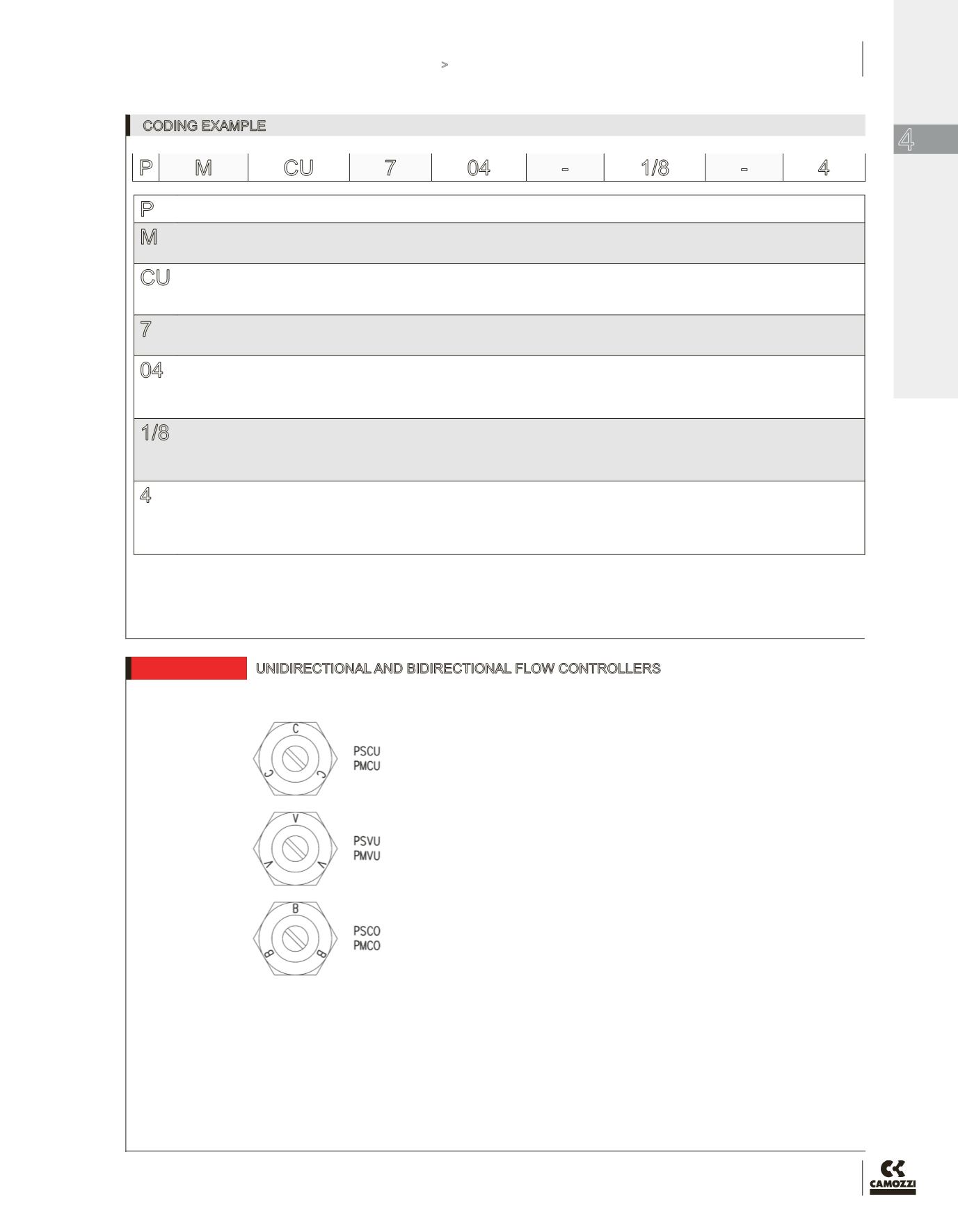
IDENTIFICATION OF DIFFERENT TYPES:
PSCU - PMCU = assembly directly on the cylinders
PSVU - PMVU = assembly directly on the valves
PSCO - PMCO = assembly directly on the cylinders or valves


