
DIMENSIONS (inches)
Mod.
A
B
F
H
L
M S
SW SW1
Z
NPTF
TMCU 53-02
1/8
5/32 0.453 0.197 1.654 0.846 0.728 0.630 0.059 1.929
TMCU 04-02
1/8
1/4 0.453 0.197 1.654 0.846 0.728 0.630 0.059 1.929
TMCU 04-04
1/4
1/4 0.453 0.256 1.732 0.846 0.709 0.630 0.059 2.008
TMCU 05-04
1/4
5/16 0.531 0.256 1.890 0.984 0.748 0.748 0.098 2.165
TMCU 05-06
3/8
5/16 0.531 0.295 1.929 0.984 0.748 0.748 0.098 2.205
TMCU 06-04
1/4
3/8 0.630 0.256 1.988 1.142 0.709 0.984 0.098 2.323
TMCU 06-06
3/8
3/8 0.630 0.295 1.988 1.142 0.709 0.984 0.098 2.323
TMCU 06-08
1/2
3/8 0.630 0.335 2.028 1.142 0.709 0.984 0.098 2.362
Meter In, Meter Out, Needle Orifice FLOW CONTROLLERS
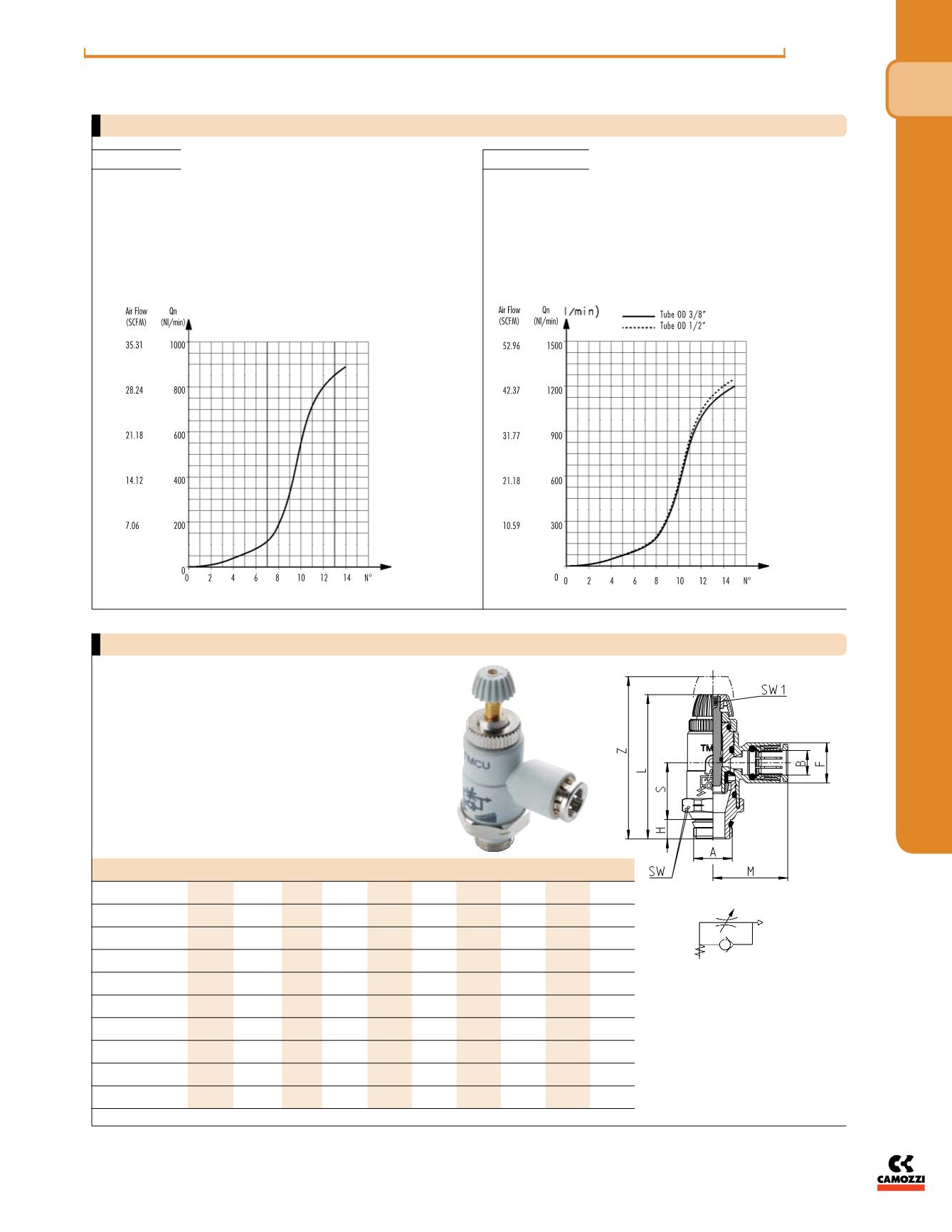
Meter-Out Valves Series TMCU
Flow Qn (Nl/min.) from 2 ® 1 with needle OPEN: 890
Flow Qn (Nl/min.) from 2 ® 1 with needle CLOSED: 460
NB: Qn is determined with a supply pressure of 6 bar and with
DP= bar at the outlet
N° = of screw turns
Tube OD 5/16”
Tube OD 3/8” - 1/2”
Flow Qn (Nl/min.) from 2 ® 1 with needle OPEN: Ø 3/8”-1200/
Ø1/2”-1250
Flow Qn (Nl/min.) from 2 ® 1 with needle CLOSED: Ø 3/8”-
600/Ø1/2”-600
NB: Qn is determined with a supply pressure of 6 bar and with
DP= bar at the outlet
N° = of screw turns
Right angle flow controller for mounting on cylinders and valves.
Knurled screw adjustment, with internal hex slot.
Ports 1/8”, 1/4”, 3/8”, 1/2” NPTF
The company reserves the right to vary models and dimensions without notice.
These products are designed for industrial applications and are not suitable for sale to the general public.
123
N P T F/ I NCH
f l ow con t ro l v a l v e s & a c c e s sor i e s
4


