
f l ow con t ro l v a l v e s & a c c e s sor i e s
4
B S P / M E T R I C
b s p/me t r i c
The company reserves the right to vary models and dimensions without notice.
These products are designed for industrial applications and are not suitable for sale to the general public.
188
Dimensions in millimeters (mm)
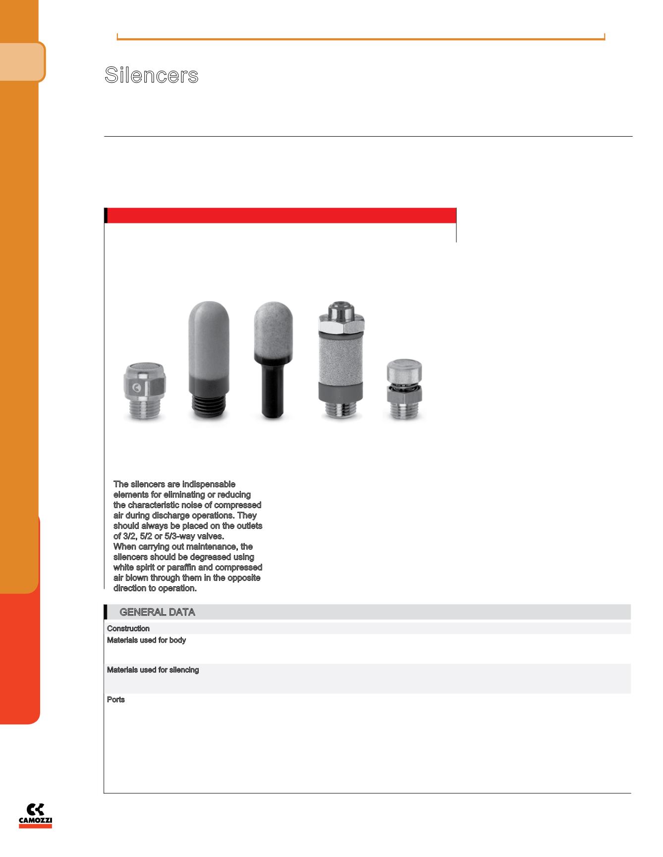
Silencers
Series: 2901 - 2903 - 2921 - 2931 - 2938 - 2939 - 2905 - RSW
Ports: M5, G1/8, G1/4, G3/8, G1/2, G3/4, G1
The silencers are indispensable
elements for eliminating or reducing
the characteristic noise of compressed
air during discharge operations. They
should always be placed on the outlets
of 3/2, 5/2 or 5/3-way valves.
When carrying out maintenance, the
silencers should be degreased using
white spirit or paraffin and compressed
air blown through them in the opposite
direction to operation.
Flow rate: determined with inlet supply 6
bar and output in atmosphere.
Noise level: determined through a test
which is carried out using a phonometer.
Placing the phonometer one meter away
from the application at the same height
for a period of ten seconds gives an
average reading of the noise generated.
GENERAL DATA
Construction
body with male and female thread
Materials used for body
2901 - 2903: brass
2921 - 2931: coppering steel
2938 - 2939: polyethylene
Materials used for silencing 2901 - 2903: stainless steel
2921 - 2931: bronze (sintered)
2938 - 2939: polyethylene
Ports
M5 - G1/8 - G1/4 - G3/8 - G1/2 - G3/4 - G1


