
The company reserves the right to vary models and dimensions without notice.
These products are designed for industrial applications and are not suitable for sale to the general public.
70
a i r p i l o t v a l v e s
3
Dimensions in millimeters (mm)
For valves Series 4, 1/4 (3-way/2-position, 5-way/2-
position or 5-w a y/3-positions).
The following is supplied :
N° 1 manifold
N° 1 pair of fixing screws per valve position
N° 3 OR seal per valve position
N° 2 guides per valve position
* Available from 2 - 6 stations
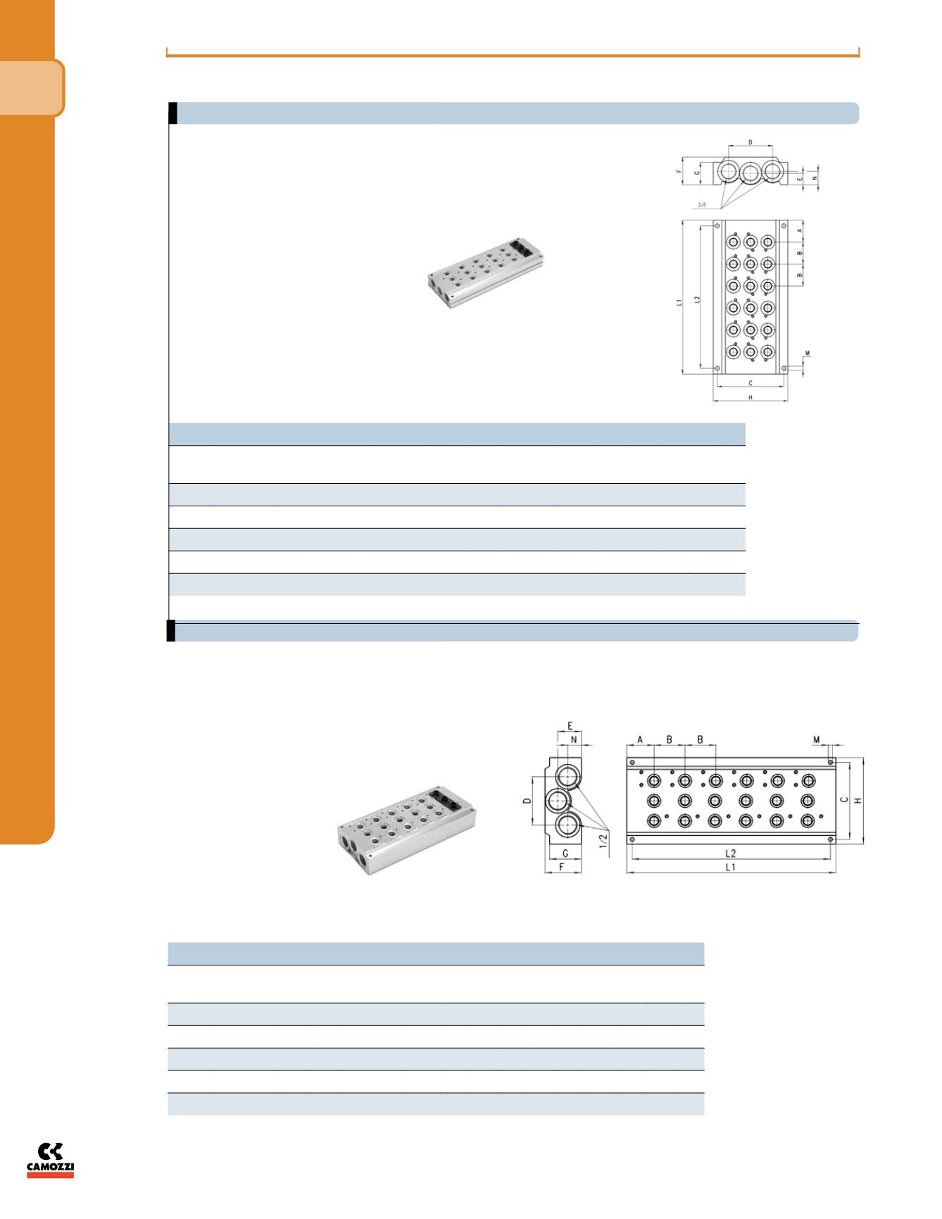
DIMENSIONS
Stations
Mod.
A
B
Inlet/Exhaust
Ports NPTF
C
D E
F
G
H L1 L2 M N
2
CNVL-42TF
28
33
3/8”
69.5 46 12 29 23.5 78 89 77 4.3 14
3
CNVL-43TF
28
33
3/8”
69.5 46 12 29 23.5 78 122 110 4.3 14
4
CNVL-44TF
28
33
3/8”
69.5 46 12 29 23.5 78 155 143 4.3 14
5
CNVL-45TF
28
33
3/8”
69.5 46 12 29 23.5 78 188 176 4.3 14
6
CNVL-46TF
28
33
3/8”
69.5 46 12 29 23.5 78 221 209 4.3 14
DIMENSIONS
Stations
Mod.
A
B
Inlet/Exhaust
Ports NPTF
C
D E
F
G H L1 L2 M N
2
CNVL-52TF
30 34
1/2”
84.5 53 26 40 35 95 94 82 4.3 15
3
CNVL-53TF
30 34
1/2”
84.5 53 26 40 35 95 128 116 4.3 15
4
CNVL-54TF
30 34
1/2”
84.5 53 26 40 35 95 162 150 4.3 15
5
CNVL-55TF
30 34
1/2”
84.5 53 26 40 35 95 196 184 4.3 15
6
CNVL-56TF
30 34
1/2”
84.5 53 26 40 35 95 230 218 4.3 15
For valves Series 4, 1/8 (3-way/2-position, 5-way/2-position
or 5-way/3-positions).
The following is supplied :
N° 1 manifold
N° 1 pair of fixing screws per valve position
N° 3 OR seal per valve position
N° 2 guides per valve position
* Available from 2 - 6 stations
Manifold base with common exhausts - Series 4 valves 1/8”
Manifold base with common exhausts - Series 4 valves 1/4”


