


 137 / 266

120
The company reserves the right to vary models and dimensions without notice.
These products are designed for industrial applications and are not suitable for sale to the general public.
FLOW CONTROL VALVES NPTF
Flow Control Valves NPTF
3
NORTH AMERICAN FITTINGS & FLOW CONTROL VALVE CATALOG
>
Release 8.6
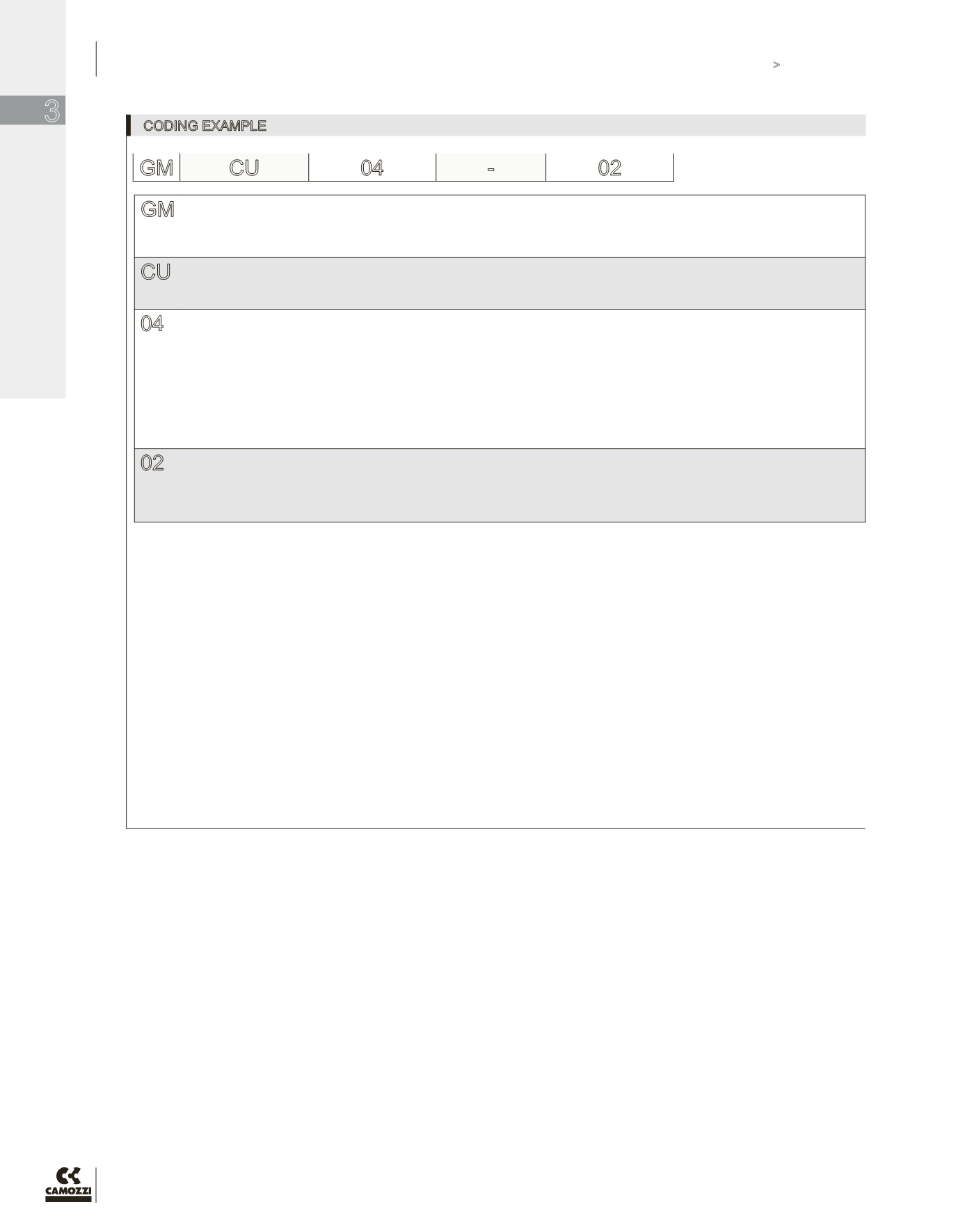
CODING EXAMPLE
GM
ACTUATION:
GM = swivel body, manual adjustment
GS = swivel body, screwdriver adjustment
M = manual adjustment, non-swivel banjo
S = screwdriver adjustment, non-swivel banjo
CU
ASSEMBLY:
CU = on cylinders (meter out)
VU = on valves (meter in)
CO = (needle orifice)
04
ATTACHMENTS
32F = 10-32 UNF Female Thread
53 = 5/32” OD Tube
02 = 1/8” OD Tube
02F = 1/8” NPTF Female Thread
04 = 1/4” OD Tube
04F = 1/4” NPTF Female Thread
05 = 5/16” OD Tube
06 = 3/8” OD Tube
06F = 3/8” NPTF Female Thread
08 = 1/2” OD Tube
08F = 1/2” NPTF Female Thread
02
Thread
32 = 10-32 UNF
02 = 1/8” NPTF
04 = 1/4” NPTF
06 = 3/8” NPTF
08 = 1/2” NPTF
To ensure the right choice of unidirectional flow controller, proceed as follows: calculate the quantity of air in Nl/min (see cylinder Table); determine the stroke time of the cylinder;
refer to graph to see which controller is the right type.
GM CU
04
-
02