


 158 / 266

141
The company reserves the right to vary models and dimensions without notice.
These products are designed for industrial applications and are not suitable for sale to the general public.
Flow Control Valves NPTF
3
NORTH AMERICAN FITTINGS & FLOW CONTROL VALVE CATALOG
>
Release 8.6
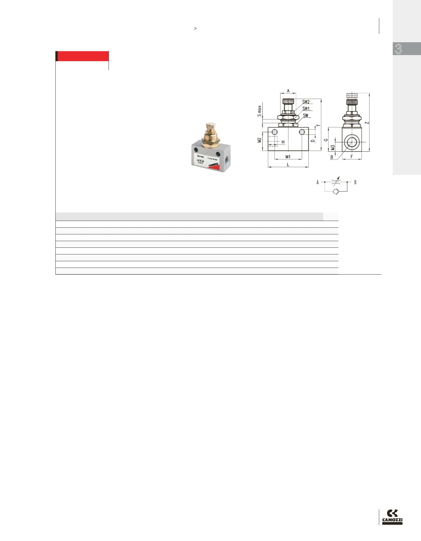
FLOW CONTROL VALVES NPTF
DIMENSIONS (in inches)
Mod.
A
B H D F
G L
M1 M2 M3
T
Z SMax SW SW1 SW2
METRIC UNF
RFU 452-M5
M10x1 10-32 .256 .165 .551 .630 1.02 .728 .520 .280 1.54 1.750 .118 .472 .551 .315
NPTF
RFU 482-02
M12X1 1/8”
.354 .177 .629 .826 1.338 .964 .649 .315 1.811 2.007 .157 .551 .669 .354
RFU 483-02
M12X1 1/8”
.354 .177 .629 .826 1.338 .964 .649 .315 1.811 2.007 .157 .551 .669 .354
RFU 444-04
M20x1.5 1/4”
.492 .255 .984 1.181 2.047 1.377 .944 .472 2.362 2.716 .275 .866 .944 .551
RFU 446-04
M20x1.5 1/4”
.492 .255 .984 1.181 2.047 1.377 .944 .472 2.362 2.716 .275 .866 .944 .551
Unidirectional flow controller Series RFU
To regulate the speed of a cylinder, the air flow from
the chamber which is being discharged must be
regulated.
For this reason, the unidirectional flow controller
must be connected as follows:
connect the threaded outlet marked A to the cylinder
inlet and the threaded outlet marked B to the valve
user port.