
177
The company reserves the right to vary models and dimensions without notice.
These products are designed for industrial applications and are not suitable for sale to the general public.
Flow Control Valves BSP
4
NORTH AMERICAN FITTINGS & FLOW CONTROL VALVE CATALOG
>
Release 8.6
FLOW CONTROL VALVES BSP
RFU 444-1/4: flow from 2 → 1 needle type OPEN = 680 Nl/min
CLOSED = 534 Nl/min
RFU 446-1/4: flow from 2 → 1 needle type OPEN = 680 Nl/min
CLOSED = 534 Nl/min
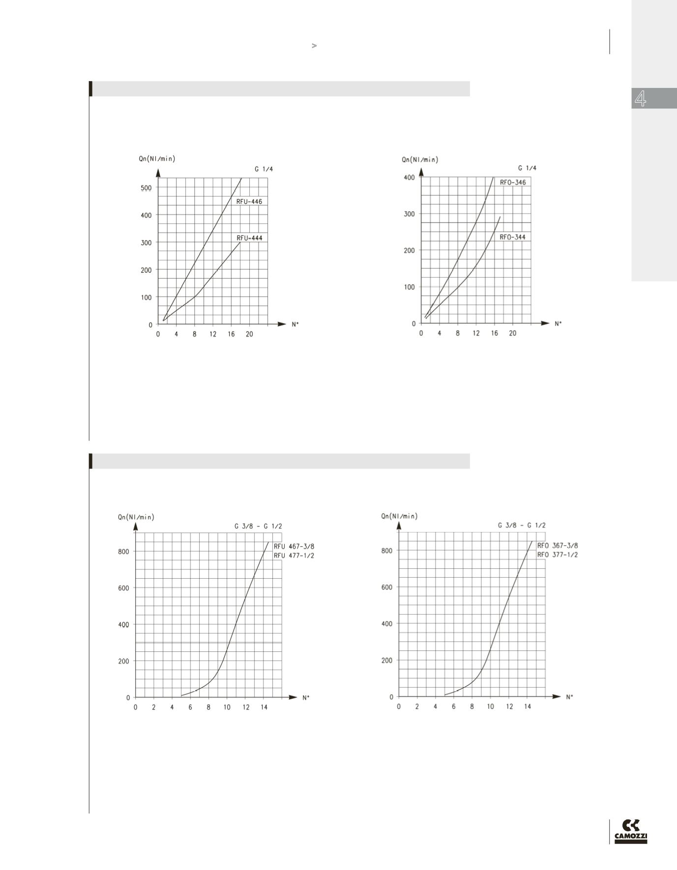
N° = number of screw turns
Note: the flow (Qn) is determined with a pressure of 6 bar at the
inlet and ΔP = 1 bar at the outlet.
RFO 344-1/4 - RFO 346-1/4
N° = number of screw turns.
Note: the flow (Qn) is determined with a pressure of 6 bar at the
inlet and ΔP = 1 bar at the outlet.
FLOW DIAGRAMS (1 → 2) - VALVES SERIES RFU / RFO - G1/4 PORTS
RFU 467-3/8: flow from 2 → 1 needle type OPEN = 1700 Nl/min
CLOSED = 1700 Nl/min
RFU 477-1/2: flow from 2 → 1 needle type OPEN = 1700 Nl/min
CLOSED = 1700 Nl/min
N° = number of screw turns
Note: the flow (Qn) is determined with a pressure of 6 bar at the
inlet and ΔP = 1 bar at the outlet.
RFO 367-3/8 - RFO 377-1/2
N° = number of screw turns
Note: the flow (Qn) is determined with a pressure of 6 bar at the
inlet and ΔP = 1 bar at the outlet.
FLOW DIAGRAMS (1 → 2) - VALVES SERIES RFU / RFO - G3/8, G1/2 PORTS


